Refined gas-liquid separator

A liquid separator and refined gas technology, which is applied in the field of gas-liquid separation device, can solve the problem of small gas content range and achieve the effect of refined gas-liquid separation

Pending Publication Date: 2019-08-02
HARBIN ENG UNIV
View PDF7 Cites 4 Cited by
  • Summary
  • Abstract
  • Description
  • Claims
  • Application Information

AI Technical Summary

Problems solved by technology

[0005] The purpose of the present invention is to provide a refined gas-liquid separator that solves the problems of applicable flow and small gas content range in the current gas-liquid separation technology field

Method used


Image

  • Refined gas-liquid separator
  • Refined gas-liquid separator
  • Refined gas-liquid separator

Examples


Embodiment Construction

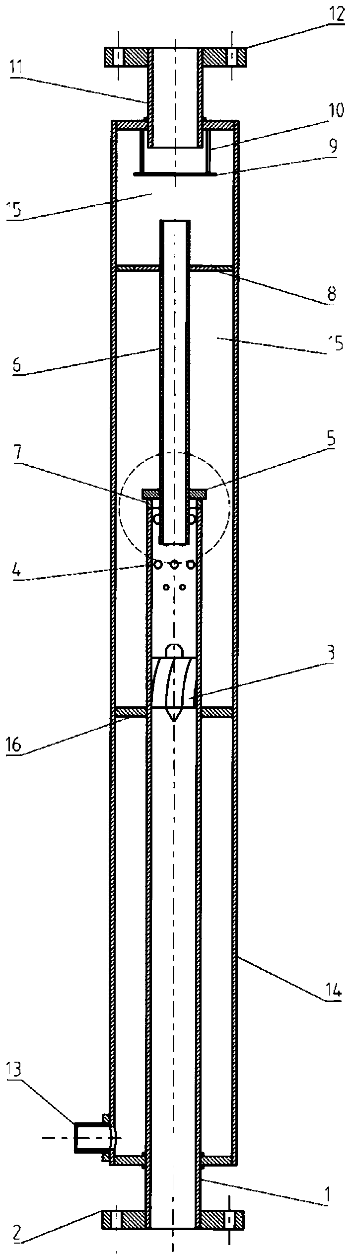
[0028] The present invention is described in more detail below in conjunction with accompanying drawing example:

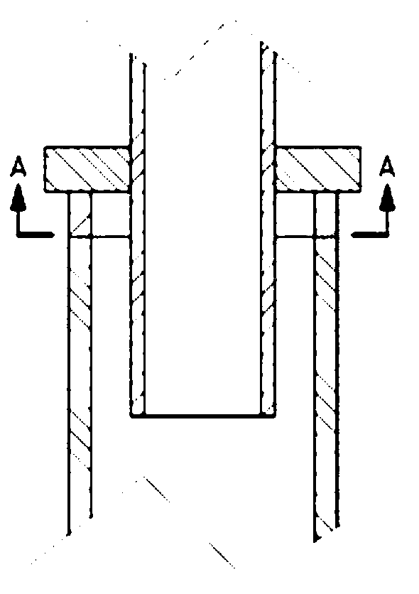
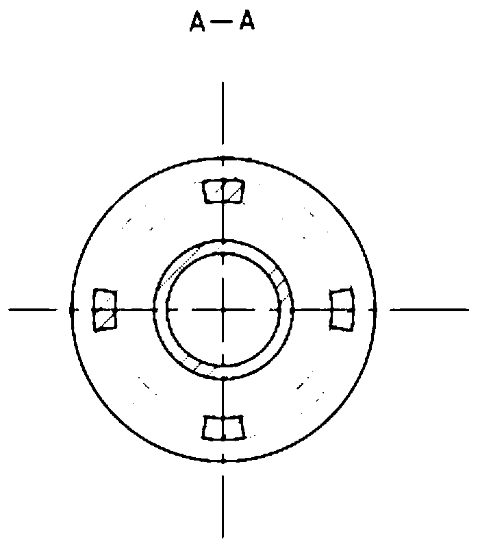
[0029] combine Figure 1-5 , a refined gas-liquid separator of the present invention, comprising: an inner cylinder 1, an inlet flange 2, an impeller 3, a liquid discharge section 4, a water retaining cap 5, a core barrel 6, a water retaining cap support strip 7, a retaining Water ring 8, separation baffle 9, separation baffle tension rib 10, separator gas phase outlet 11, outlet flange 12, separator liquid phase outlet 13, outer cylinder 14, gravity separation chamber 15, shockproof strip 16 . Its main structure is composed of mutually nested cylinder structures, namely: outer cylinder 14, inner cylinder 1, and core cylinder 6. The gas phase outlet 11 and liquid phase outlet 13 of the separator are respectively located on the top of the outer cylinder 14. with the bottom end.

[0030]The inlet end of the gas-liquid mixture in the inner cylinder 1 of the separa...


PUM


Abstract

The invention aims at providing a refined gas-liquid separator which comprises an outer barrel body, an inner barrel body and a core barrel, wherein the inner barrel body extends into the outer barrelbody; the lower end part of the inner barrel body is left at the outer part of the outer barrel body; the core barrel is located in the outer barrel body; the lower end part of the core barrel extends into the inner barrel body; a water retaining ring and a water retaining cap are respectively mounted at the outer part of the core barrel; the water retaining ring is fixed between the core barreland the outer barrel body; the water retaining cap is connected with the inner barrel body by a water retaining cap supporting rod; an impeller is mounted in the inner barrel body; a liquid dischargesection is arranged on the inner barrel body above the impeller; liquid discharge holes are formed in the liquid discharge section; a separator liquid-phase outlet is formed in the lower end part of the outer barrel body; a separator gas-phase outlet is formed in the top of the outer barrel body; a gravity separation chamber is formed in each of inner spaces of the outer barrel body, which are located above the water retaining ring and below the water retaining ring. According to the refined gas-liquid separator, gas-liquid mixture can be efficiently separated in a refined manner through three-time separation within the wide flow range and under different corrected flow rates of a gas phase and a liquid phase, in particular to an oscillatory flow pattern.

Description

technical field [0001] The invention relates to a gas-liquid separation device, in particular to a gas-liquid separation device in the field of nuclear energy. Background technique [0002] Gas-liquid separation technology is a widely used technology in the current nuclear energy development process, such as: steam drying in steam generators, separation of fission gases in reactors. With the further deepening of nuclear energy development and utilization, the gas-liquid mixture to be separated gradually presents the characteristics of wide process flow, large gas content range, and diversified flow patterns, which poses new challenges to the existing gas-liquid separation technology. [0003] At present, there are many kinds of gas-liquid separators that have been practically applied. According to the separation principle they use, they can be roughly divided into: gravity gas-liquid separator, cyclone gas-liquid separator, collision gas-liquid separator, multi-principle Ga...

Claims


Application Information

Patent Timeline
IPC IPC(8): B01D45/16B01D45/08B01D45/02B01D19/00
CPCB01D19/00B01D45/02B01D45/08B01D45/16
Inventor 范广铭王刚阎昌琪曾晓波刘安泰徐浚修
Owner HARBIN ENG UNIV
Why Eureka
Try Eureka