splash deflector

A diversion device and anti-splash technology, which is applied in the direction of metal processing equipment, maintenance and safety accessories, metal processing machinery parts, etc., can solve the problem that cooling water is easy to splash out of the water tank, so as to avoid splashing out of the water tank, ensure cleanliness, easy to get effect

Active Publication Date: 2020-05-29
CHONGQING HONGGANG CNC MACHINE TOOL
View PDF8 Cites 0 Cited by
  • Summary
  • Abstract
  • Description
  • Claims
  • Application Information

AI Technical Summary

Problems solved by technology

[0004] The present invention intends to provide an anti-splash diversion device to solve the problem that cooling water easily splashes out of the water tank in CNC lathes with inclined beds

Method used


Image

  • splash deflector
  • splash deflector
  • splash deflector

Examples


Embodiment 1

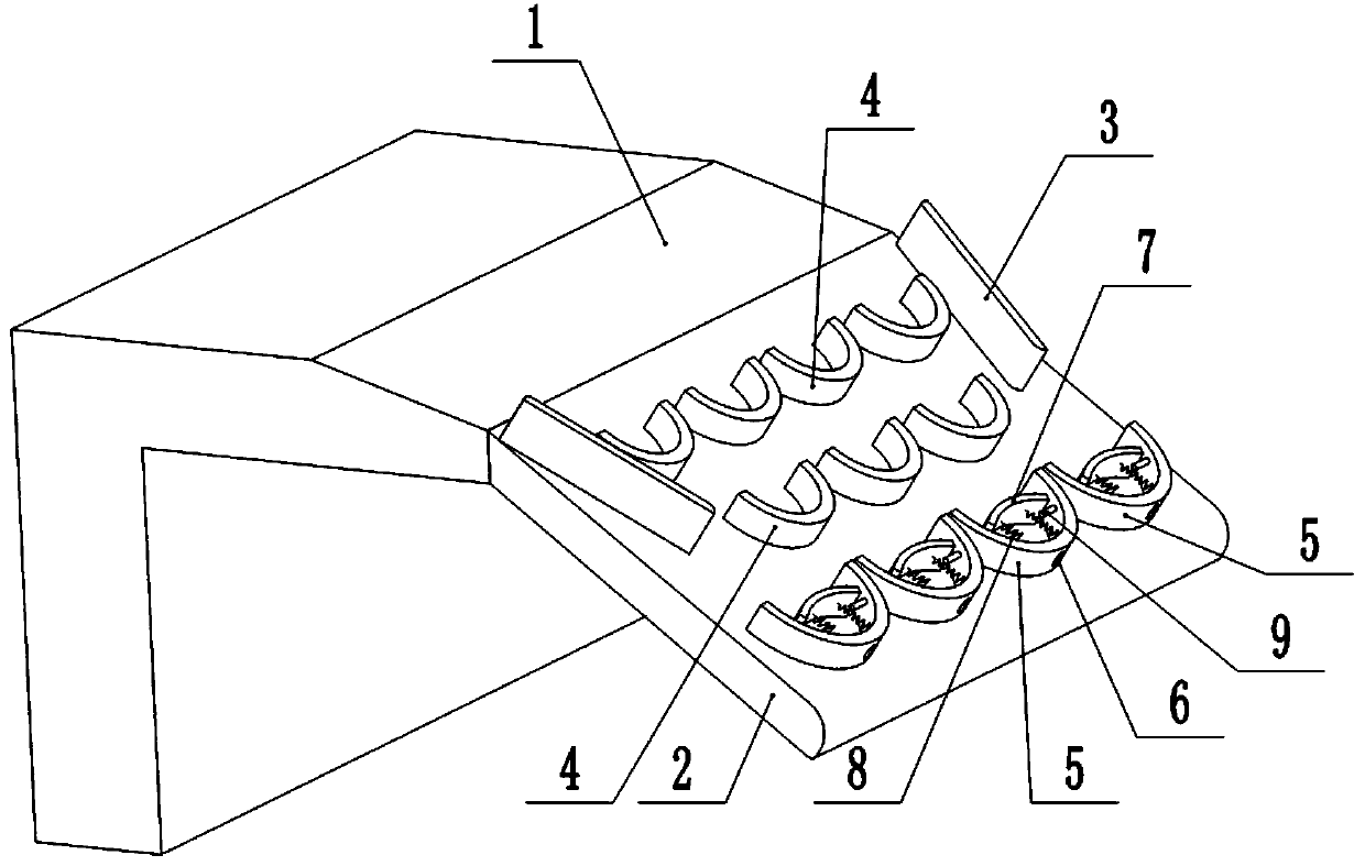
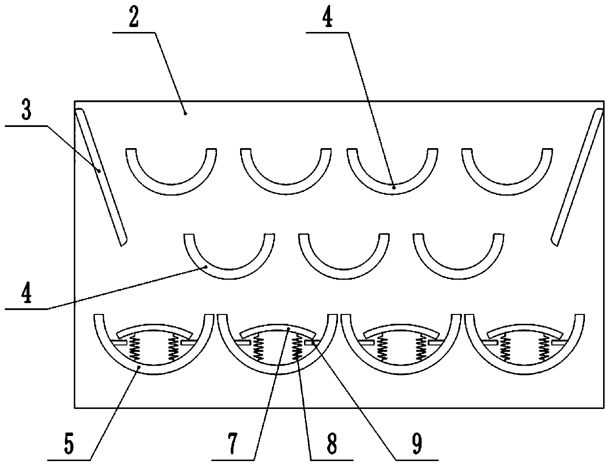
[0036] This embodiment is basically as figure 1 and figure 2 As shown, the anti-splash deflector includes a deflector 2 fixedly connected to the right end of the self-flowing part 1 at the low point of cooling water, the deflector 2 is arranged obliquely, and the left end of the deflector 2 is higher than the right end. The inclination angle of flow plate 2 is 45°. The side wall of the deflector 2 is provided with two deflectors 3 and several spoilers 4, the two deflectors 3 are in an inverted figure-eight shape, and the spoilers 4 are arc-shaped. In this embodiment, the number of baffles 4 is seven, and the seven baffles 4 are divided into upper and lower layers. The quantity of 4 is four, and the quantity of the spoiler 4 of the lower floor is three.

[0037] Below the two ends of the diversion plate 3 and the lower baffle 4 are provided with an arc-shaped diverter plate 5, the diverter plate 5 is fixedly connected to the diverter plate 2, and the diverter plate 5 is use...

Embodiment 2

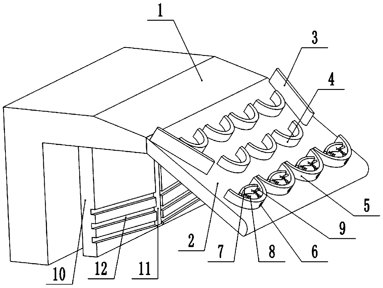
[0042] The difference between this embodiment and Embodiment 1 is that: figure 2 and image 3 As shown, the splash-proof deflector device further includes a splash-proof plate 10 , which is located on the left side of the deflector 2 , and the splash-proof plate 10 is fixedly connected with the cooling water low point artesian part 1 . A confluence groove 11 and a plurality of drainage grooves 12 are provided on the right side wall of the splash guard 10. In this embodiment, there are six drainage grooves 12 in total. The confluence groove 11 is vertically arranged and the confluence groove 11 is located at the center of the splash guard 10, the diversion groove 12 is connected with the confluence groove 11, and the diversion groove 12 is arranged symmetrically along the vertical center line of the confluence groove 11, and the diversion groove 12 is close to One end of the confluence groove 11 is lower than the end of the drainage groove 12 away from the confluence groove 1...

Embodiment 3

[0045] The difference between this embodiment and Embodiment 1 is that: figure 2 , Figure 4 and Figure 5 As shown, the splash-proof deflector device further includes a splash-proof plate 10 , which is located on the left side of the deflector 2 , and the splash-proof plate 10 is fixedly connected with the cooling water low point artesian part 1 . The bottom end of the splash guard 10 is a V-shaped structure, and the splash guard 10 is provided with a first splash roller 13 and a second splash roller 14 arranged symmetrically along the vertical center line of the splash guard 10, and the first splash roller 13 and the outer walls of the second anti-splash roller 14 are in contact with the V-shaped surface of the splash-proof plate 10, and the ends of the first anti-splash roller 13 and the second anti-splash roller 14 that are close to each other are inclined downward. Specifically, a mounting block 15 is fixedly connected to the side wall and the V-shaped surface of the s...


PUM


Abstract

The invention relates to the technical field of machine tool splash-proof equipment, and particularly discloses a splash-proof flow guide device. The splash-proof flow guide device comprises a flow guide plate which is positioned at the end part of a cooling water low-point self-flowing part, two drainage plates and a plurality of flow baffle plates are arranged on the side wall of the flow guideplate, the two drainage plates are in an inverted splayed shape, arc-shaped flow-division plates are arranged below the drainage plates and the two ends of the flow baffle plates correspondingly, theflow-division are used for containing cooling water flowing from the drainage plates and the flow baffle plates, water passing holes are formed in the middles of the flow-division plates, flow slowingmechanisms are arranged on the inner side walls of the flow-division plates, the flow slowing mechanisms comprise flow slowing pieces, elastic pieces and limiting pieces, the slow flowing pieces arefixedly connected with the flow-division plates through the elastic pieces, the flow slowing pieces are located above the water passing holes, one ends of the limiting pieces are fixedly connected with the flow-division plates, and the other ends of the limiting pieces abuts against the lower surfaces of the slow flowing pieces. According to the splash-proof flow guide device, the impact force ofthe cooling water can be reduced, the cooling water is distributed, so that the cooling water is divided into a plurality of strands of water and flows into the water tank, then flow slowing and division of the cooling water are realized, and then the cooling water is prevented from splashing out of the water tank.

Description

technical field [0001] The invention relates to the technical field of splash-proof equipment for machine tools, and specifically discloses a splash-proof flow guide device. Background technique [0002] Slanted bed CNC lathe is a high-precision, high-efficiency automatic machine tool, equipped with multi-station turret or power turret, has a wide range of process performance, and can process straight cylinders, oblique cylinders, arcs and various threads, Complicated workpieces such as grooves and worms have various compensation functions such as linear interpolation and circular interpolation. [0003] During the working process of the inclined bed CNC machine tool, the cooling water used by the saddle parts installed on the guide rail flows naturally into the water tank located under the middle part of the inclined bed through the low point artesian part of the cooling water on the inclined bed body. However, due to The cutter head running at high speed drives the coolin...

Claims


Application Information

Patent Timeline
Patent Type & Authority Patents(China)
IPC IPC(8): B23Q11/12
CPCB23Q11/12
Inventor 汪传宏
Owner CHONGQING HONGGANG CNC MACHINE TOOL
Why Eureka
Try Eureka