
Photoelectricity coded lock system and control method

A combination lock and photoelectric technology, which is applied in the field of photoelectric combination locks, can solve problems such as insufficient security, limited number of passwords, and limited number of password digits, and achieve the effects of avoiding password leakage, high security, and good interactivity

Active Publication Date: 2019-08-02
XI'AN UNIVERSITY OF ARCHITECTURE AND TECHNOLOGY
View PDF6 Cites 3 Cited by
  • Summary
  • Abstract
  • Description
  • Claims
  • Application Information

AI Technical Summary

Problems solved by technology

[0003] At present, the combination locks commonly used in the market are mainly electronic combination locks, which have the advantages of convenient setting and unlocking, and no need to carry keys; but there are also many defects, such as: the number of password digits and the number of codes per person Limited, the number of composed passwords is limited, and the security is not high enough. It needs to be accompanied by a key lock for double insurance; increasing the number of passwords to improve security will result in longer passwords that are difficult to remember. The above defects make electronic combination locks widely used restricted
In addition, most electronic combination locks use built-in software and algorithms to ensure the security of the key. After the user enters the password, it is directly received by the software in the control center in plain text. There is no encryption in the middle, and it is easy to be cracked. The built-in software directly obtains the plain text password. Make the software's built-in encryption algorithm unable to play the role of password protection

Method used


Image

  • Photoelectricity coded lock system and control method
  • Photoelectricity coded lock system and control method
  • Photoelectricity coded lock system and control method

Examples


Embodiment Construction

[0047] The present invention will be described in further detail below in conjunction with the accompanying drawings and specific embodiments.

[0048] In order to make the purpose, technical effects and technical solutions of the embodiments of the present invention more clear, the technical solutions in the embodiments of the present invention are clearly and completely described below in conjunction with the accompanying drawings in the embodiments of the present invention; obviously, the described embodiments It is a part of the embodiment of the present invention. Based on the disclosed embodiments of the present invention, other embodiments obtained by persons of ordinary skill in the art without making creative efforts shall all fall within the protection scope of the present invention.

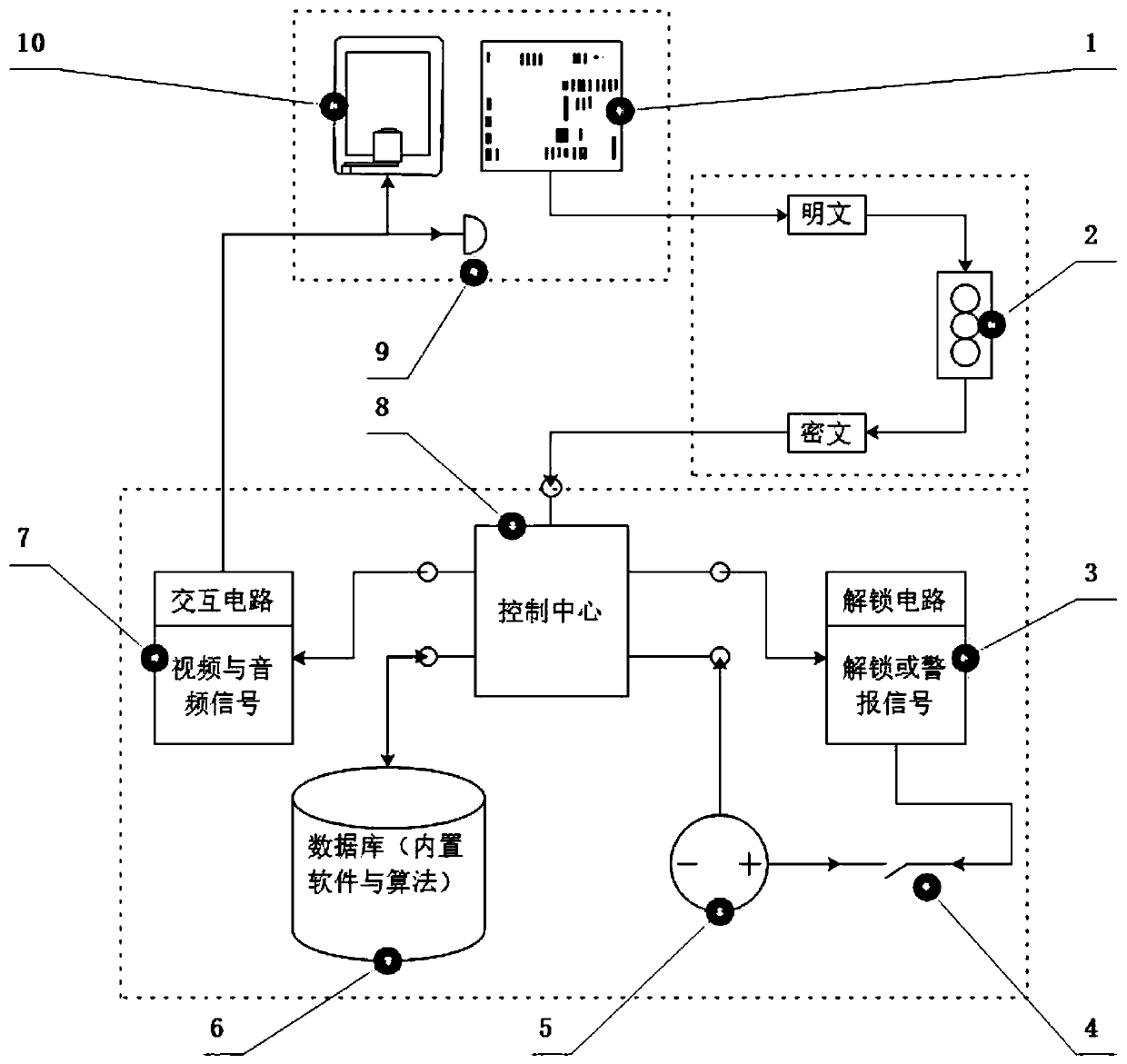
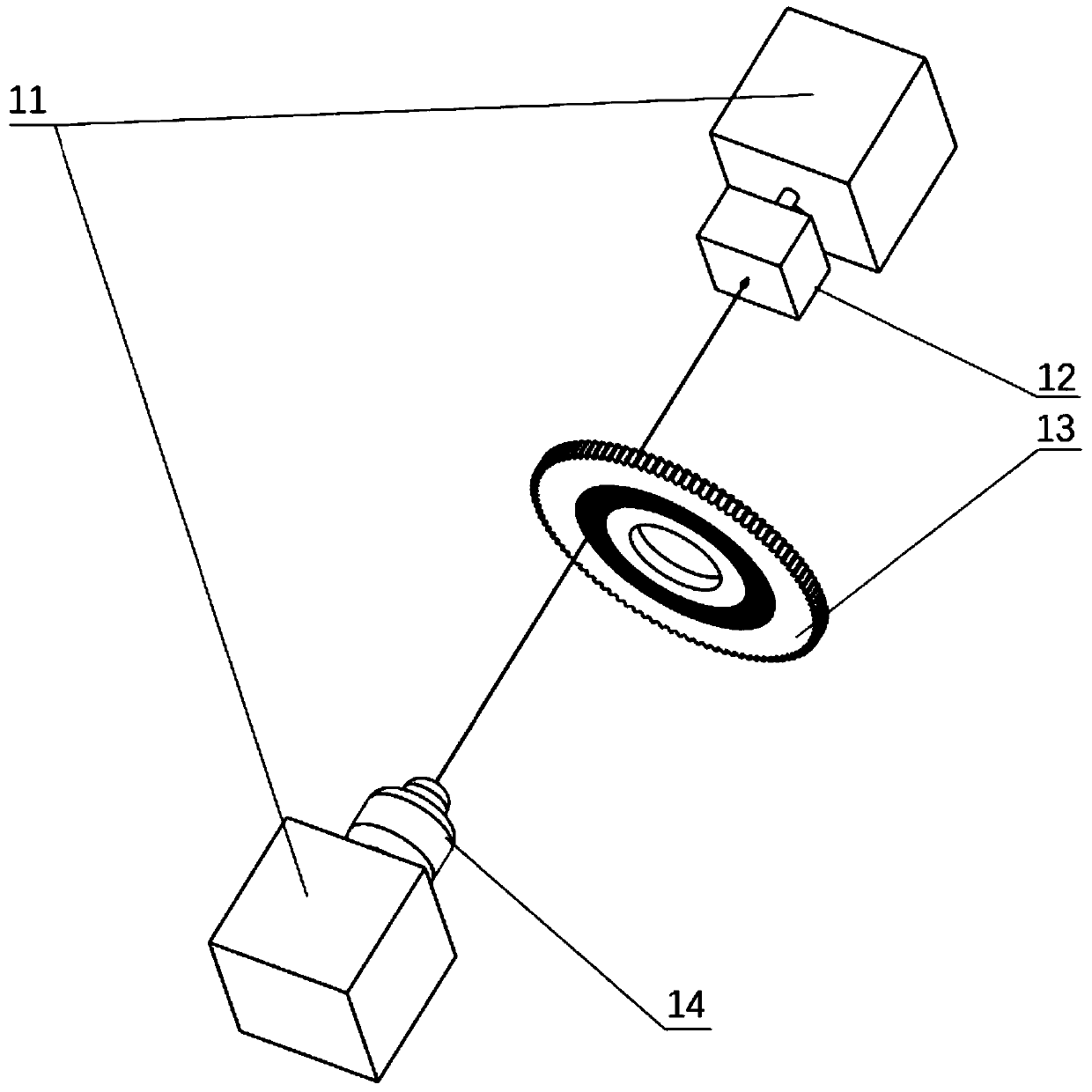
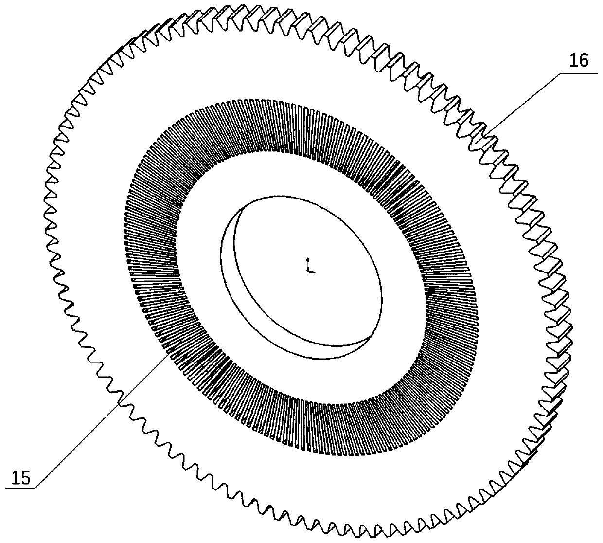
[0049] see Figure 1 to Figure 3 , a kind of photoelectric combination lock system of the embodiment of the present invention, comprises:

[0050] The input module 1 is used to input...


PUM


Abstract

The invention discloses a photoelectricity coded lock system and a control method. The system comprises an input module used for inputting cleartext password information, a photoelectric converter module used for converting the cleartext password information into ciphertext password information, a control center module used for receiving ciphertext password information and transmitting the ciphertext password information to a database module and sending out a control instruction according to comparison result information fed back by the database module, the database module used for comparing the input ciphertext password information with pre-stored password information and feeding back the comparing result to the control center module, an unlocking circuit module used for receiving the control instruction sent out by the control center module and controlling a coded lock body to be unlocked, and an interchange circuit module used for receiving the control instruction sent out by the control center module and feeding back wrong password inputting information or alarm information. Before embedded software is input, password plaintexts are encrypted, and the problem that due to the fact that the embedded software and an algorithm are cracked, and passwords are leaked is solved.

Description

technical field [0001] The invention belongs to the technical field of photoelectric combination locks, and in particular relates to a photoelectric combination lock system and a control method. Background technique [0002] There are about several hundred kinds of electronic combination locks that have been published in the world and are in patent status, and there are dozens of photoelectric combination locks and mechanical combination locks. In science, this kind of password is a password with a weak security level. Therefore, present combination lock, in order to improve the safety of lock, generally all adds key lock as auxiliary and carries out double insurance. At present, the main way to improve security is to increase the number of passwords or increase the bit code on each bit. After increasing the number of passwords or increasing the bit code, it is more difficult to remember, and it takes longer to unlock, which directly affects the practicability of the combin...

Claims


Application Information

Patent Timeline
Patent Type & Authority Applications(China)
IPC IPC(8): E05B47/00E05B49/00G07C9/00
CPCE05B47/0001E05B49/00G07C9/00817
Inventor 蔡安江张栋鹏张学锋
Owner XI'AN UNIVERSITY OF ARCHITECTURE AND TECHNOLOGY
Learn More