Cement retainer

A technology of cement and central pipe, which is applied in wellbore/well components, earthwork drilling, sealing/isolation, etc., and can solve problems such as water flooding in oil layers, water content in oil wells, casing leakage, etc.

Pending Publication Date: 2019-08-02
CHENGDU INNOX TECH CO LTD
View PDF0 Cites 0 Cited by
  • Summary
  • Abstract
  • Description
  • Claims
  • Application Information

AI Technical Summary

Problems solved by technology

[0002] In the middle and late stages of oilfield development, due to the corrosion and perforation of the casing above the oil well cement return height, the cement cementing section leaks, causing the formation water in the oil layer adjacent to the high-pressure water layer to flow into the wellbore, or the energy of the oil layer drops adjacent to the high-pressure water layer and the oil layer. Water-bearing or water-flooded oil layers bring serious difficulties to oil field development
At present, some old oil wells that have been in production for many years have long-term high water cuts and are in a closed state. Analysis and judgment: First, after long-term exploitation, the casing of the oil layer may be corroded and perforated, and the leakage of the casing may cause water flooding in the oil layer; , forming a water head cone with the oil layer of the well and causing water flooding of the oil layer
Third, there may be a high-pressure water layer and the oil layer near the oil layer, which may lead to water flooding of the oil layer
[0004] The cement retainer has been used for many years. The traditional cement retainer is made of metal, and it is lowered into the well through the drill pipe or tubing. Although the conventional cement retainer has good sealing performance, high pressure difference resistance and long sealing time, It can also be milled, but it is easy to cause the liquid to flow back during work, thereby damaging the equipment

Method used


Image

  • Cement retainer
  • Cement retainer
  • Cement retainer

Examples


Embodiment Construction

[0038] The principles and features of the present invention are described below in conjunction with the accompanying drawings, and the examples given are only used to explain the present invention, and are not intended to limit the scope of the present invention.

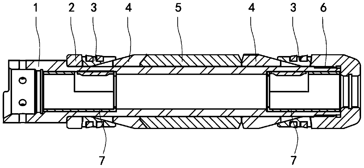
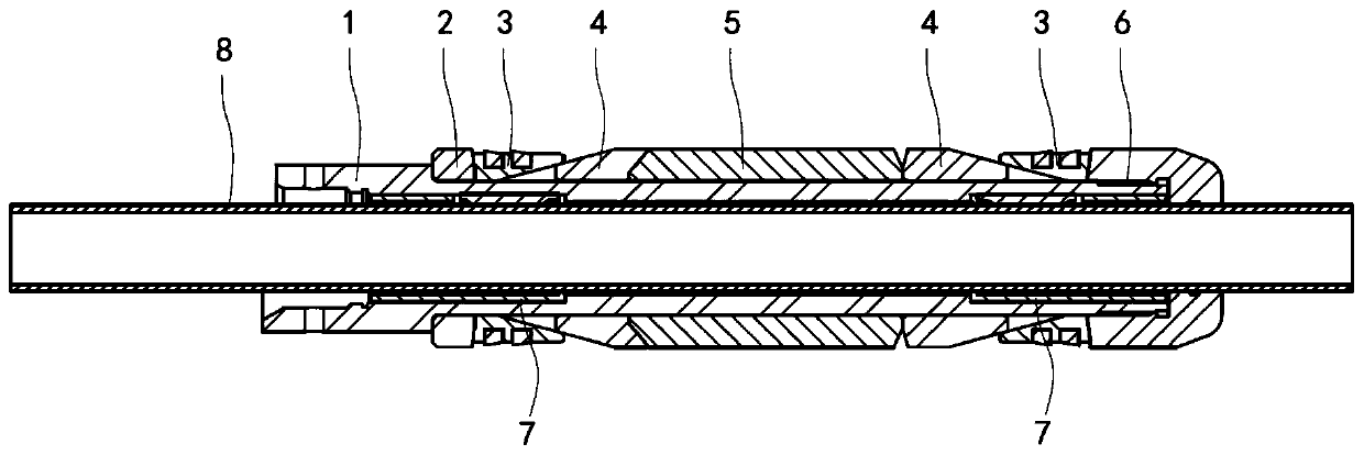
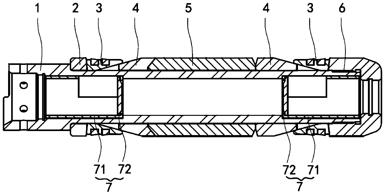
[0039] Embodiment 1 of the present invention is a cross-sectional view of the open state of the one-way valve, see figure 1 , figure 2 with image 3 .

[0040] A cement retainer, comprising a central pipe 1 and one end of the central pipe 1 is fixedly connected with a lower joint 6, the central pipe 1 is provided with a sealing anchoring structure, and one end of the sealing anchoring structure is in contact with the lower joint 6, A push ring 2 is provided between the other end of the sealing anchor structure and the other end of the central tube 1; a one-way valve 7 is provided at both ends of the central tube 1, and the cut-off directions of the two one-way valves 7 are both facing the central tube 1 The midd...


PUM


Abstract

The invention discloses a cement retainer which comprises a central pipe and a lower joint fixedly connected to one end of the central pipe, a sealing anchoring structure sleeves the central pipe in the circumferential direction, one end of the sealing anchoring structure abuts against the lower joint, and a push ring is arranged between the other end of the sealing anchoring structure and the other end of the central pipe; and one-way valves are arranged at the two ends in the central pipe respectively, and when the one-way valves are in a conducting state, an inserting pipe used for sealingslurry pouring penetrates through the one-way valves and the lower joint. During setting, an adapter in a setting tool is adaptively connected with one end of the central pipe, the inserting pipe usedfor sealing slurry pouring is inserted into the central pipe at the same time and extends out of the lower joint, and when the cement retainer reaches a set position, the sealing slurry pouring operation is directly carried out through the inserting pipe at the moment. After the grouting operation is completed, the inserting pipe is recovered. After the inserting pipe leaves the cement retainer,the one-way valves are completely in a closed state, blind blocking is formed in the one-way valves, and two-way pressure bearing is realized.

Description

technical field [0001] The invention relates to the field of oil well construction, in particular to a cement retainer. Background technique [0002] In the middle and late stage of oilfield development, due to the corrosion and perforation of the casing above the oil well cement return height, the cement cementing section leaks, causing the formation water in the oil layer adjacent to the high-pressure water layer to flow into the wellbore, or the energy of the oil layer drops adjacent to the high-pressure water layer and the oil layer. Water-bearing or water-flooded oil layers bring serious difficulties to oil field development. At present, some old oil wells that have been in production for many years have long-term high water content and are in the state of shutting down. Analysis and judgment: First, after long-term exploitation, the oil layer casing may be corroded and perforated, and casing leakage may cause oil layer water flooding; , forming a water head cone with ...

Claims


Application Information

Patent Timeline
Patent Type & Authority Applications(China)
IPC IPC(8): E21B33/13
CPCE21B33/13
Inventor 袁猷曾琦军
Owner CHENGDU INNOX TECH CO LTD
Why Eureka
Try Eureka