MIMO antenna array using electromagnetic meta-surface covering layer

A covering layer and metasurface technology, applied in the directions of antenna, antenna coupling, antenna grounding device, etc., can solve the problems of large space and inapplicability, and achieve the effect of good decoupling effect and easy processing.

Inactive Publication Date: 2019-08-02
UNIV OF SCI & TECH OF CHINA
View PDF3 Cites 9 Cited by
  • Summary
  • Abstract
  • Description
  • Claims
  • Application Information

AI Technical Summary

Problems solved by technology

[0005] Electromagnetic bandgap structure: The electromagnetic bandgap structure prevents the propagation of coupled waves to reduce coupling, but because the electromagnetic bandgap structure requires multiple cycles and takes up a large space, it is not applicable when the antenna element spacing is small

Method used


Image

  • MIMO antenna array using electromagnetic meta-surface covering layer
  • MIMO antenna array using electromagnetic meta-surface covering layer
  • MIMO antenna array using electromagnetic meta-surface covering layer

Examples


example 1

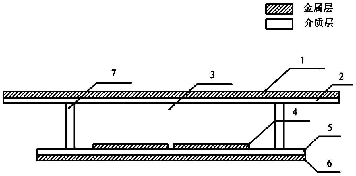
[0041] Such as Figure 1-5 As shown, the metasurface-based decoupling antenna array of the present invention includes a metasurface covering layer, an air layer, and an antenna array layer. The metasurface covering layer is composed of an upper covering layer 1 and a metasurface dielectric layer 2. The antenna array The layer is composed of a metal patch layer 4, an antenna dielectric layer 5 and a metal floor layer 6. The antenna dielectric layer 5 is arranged between the metal patch layer 4 and the metal floor layer 6, and air is set between the supersurface covering layer and the antenna array layer. Layer 3, the metamaterial cover layer is separated from the antenna array layer by the support structure 7.

[0042] Processing method of the present invention:

[0043] First make the antenna array layer, with a dielectric constant of 2.2, a thickness of 0.508mm, a length of 99mm, and a width of 70mm, the upper and lower sides of the antenna dielectric layer 5 are respectivel...

example 2

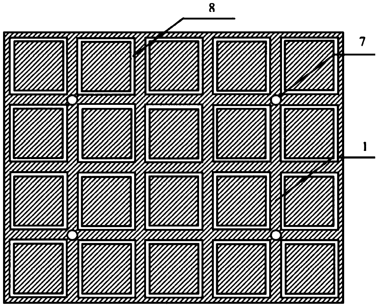
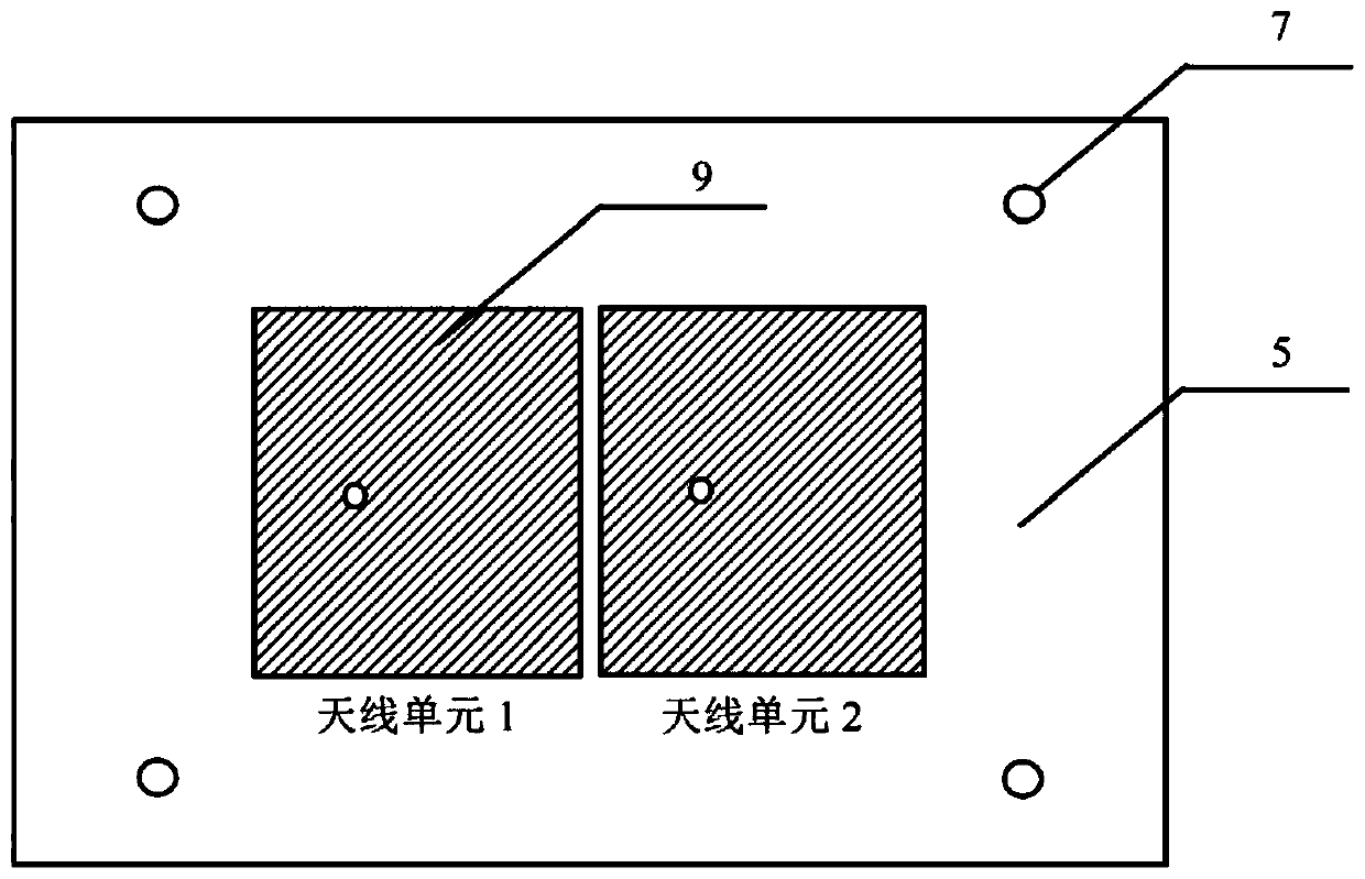
[0048] This example 2 still uses the supersurface covering layer used in Example 1, but the side length of the square ring gap of the basic unit of the covering layer becomes 21.1mm, and the metal patch of the antenna array layer is composed of two patch units of the same size arranged on the H surface composition (such as Figure 5 , Figure 6 ). Finally, the S parameter results are obtained as Figure 8a , Figure 8b As shown, it can be seen that the S21 in the antenna frequency band is greatly reduced, that is, the decoupling effect of the MIMO antenna is successfully realized.


PUM


Abstract

The invention discloses a MIMO antenna array using an electromagnetic meta-surface covering layer. The MIMO antenna array comprises a meta-surface covering layer and an antenna array layer. The meta-surface covering layer comprises an upper covering layer and a meta-surface dielectric layer. The antenna array layer comprises a metal patch layer, an antenna dielectric layer and a metal floor layer.The antenna dielectric layer is arranged between the metal patch layer and the metal floor layer. An air layer is arranged between the meta-surface covering layer and the antenna array layer, and themeta-material covering layer and the antenna array layer are separated by a support structure. The upper covering layer comprises 20 basic units periodically arranged in 4 rows and 5 columns. The metal patch layer comprises two patch cells of the same size arranged on the E-plane or the H-plane. The array having quite close spacing between elements can be decoupled and the E-plane and H-plane coupled antenna array can be greatly decoupled and processing is easy.

Description

technical field [0001] The invention relates to a wireless communication technology, in particular to a MIMO antenna array using an electromagnetic supersurface covering layer, which is a new solution for improving the isolation of a microstrip MIMO antenna. Background technique [0002] With the rapid development of wireless communication technology, the channel capacity required for communication between terminals has been greatly increased. The traditional single-input single-output communication mode has been difficult to meet the high-speed and large-capacity communication needs. The MIMO technology is proposed to solve this problem. . Recently, with the rapid development of 5G communication technology to practical use, massive MIMO technology is considered to be one of the key technologies to solve 5G communication. Compared with traditional MIMO, massive MIMO requires more array elements and is limited by In the application scenario, the distance between the array el...

Claims


Application Information

Patent Timeline
Patent Type & Authority Applications(China)
IPC IPC(8): H01Q15/00H01Q1/52H01Q1/48H01Q1/38H01Q1/50
CPCH01Q1/38H01Q1/48H01Q1/50H01Q1/52H01Q15/0086
Inventor 陈畅陈卫东栾昊泽张倾远
Owner UNIV OF SCI & TECH OF CHINA
Why Eureka
Try Eureka