Concentric thin-wall steel pipe welding machine

A thin-walled steel pipe and welding machine technology, applied in welding equipment, welding equipment, auxiliary welding equipment, etc., can solve problems such as time-consuming, concentricity deviation of thin-walled steel pipes, and large heat generated at welding parts.

Active Publication Date: 2019-08-06
GUANGDONG UNIV OF TECH
View PDF9 Cites 0 Cited by
  • Summary
  • Abstract
  • Description
  • Claims
  • Application Information

AI Technical Summary

Problems solved by technology

This way, due to the step-by-step operation, not only takes a lot of time, but also has low production efficiency, and it is easy to cause a large deviation in the con...

Method used


Image

  • Concentric thin-wall steel pipe welding machine
  • Concentric thin-wall steel pipe welding machine
  • Concentric thin-wall steel pipe welding machine

Examples


Embodiment Construction

[0029] The following will clearly and completely describe the technical solutions in the embodiments of the present invention with reference to the accompanying drawings in the embodiments of the present invention. Obviously, the described embodiments are only some, not all, embodiments of the present invention. Based on the embodiments of the present invention, all other embodiments obtained by persons of ordinary skill in the art without making creative efforts belong to the protection scope of the present invention.

[0030] In order to enable those skilled in the art to better understand the solution of the present invention, the present invention will be further described in detail below in conjunction with the accompanying drawings and specific embodiments.

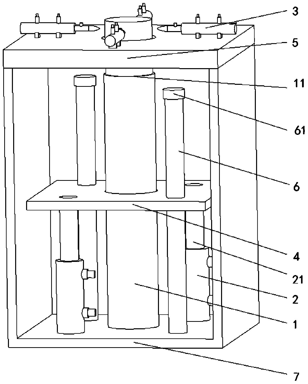
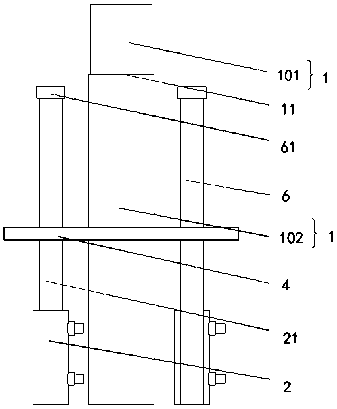
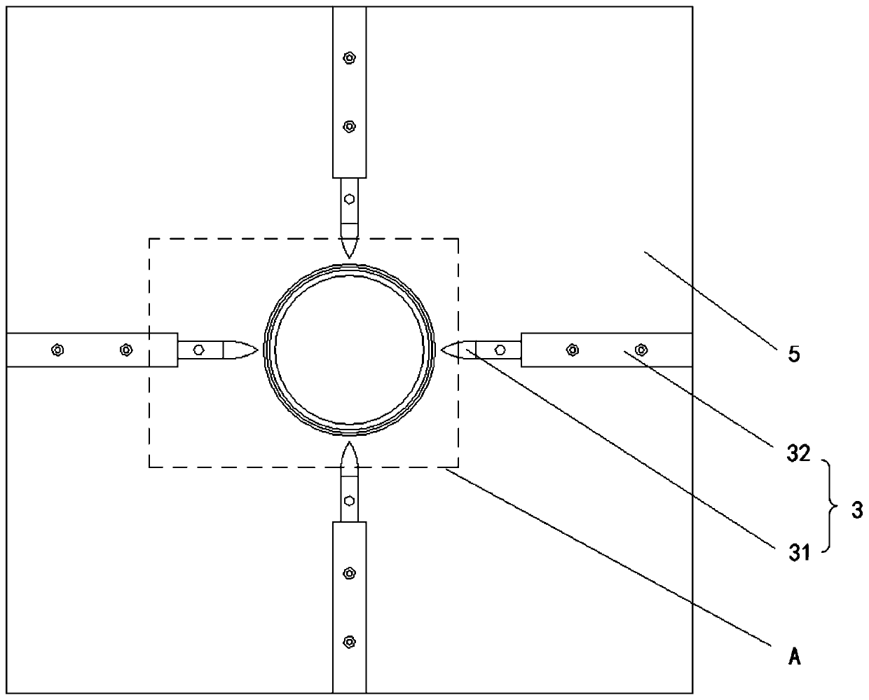
[0031] Please refer to Figure 1 to Figure 6 , figure 1 Schematic diagram of the structure of the concentric thin-walled steel pipe welding machine provided by the embodiment of the present invention; figure 2 fo...


PUM


Abstract

The invention discloses a concentric thin-wall steel pipe welding machine. The concentric thin-wall steel pipe welding machine comprises a welding column and a plurality of welding heads, wherein thewelding column is vertical arranged, provided with a cylindrical outer wall, and is used for sleeving two welded steel pipes, and the welding columns are horizontally arranged, and are distributed inan annular array by taking a center axis of the welding column as the center so as to realize simultaneous gathering and dispersion; and the welding head and the welding columns are connected to a positive electrode and a negative electrode of a power supply respectively. When all the welding heads are gathered by taking the center axis of the welding column as the center until the front ends of the welding heads are in contact with the welded steel pipes located on the periphery, the welding heads are connected with the welding column through the welded steel pipes, a circuit is closed, and electric welding of the welded steel pipes is realized by utilizing the resistance heat at the welding position; and the heat generated at the welding position can be adjusted by controlling the welding current and the duration of the welding head being in contact with the welded steel pipes by the concentric thin-wall steel pipe welding machine, and the welded steel pipes are prevented from beingpenetrated by excessive heat of the welding position of the welded steel pipes.

Description

technical field [0001] The invention relates to the field of steel production, in particular to a welding machine for concentric thin-walled steel pipes. Background technique [0002] Steel pipes, especially thin-walled steel pipes, are mostly welded by electrode arc welding. During operation, workers clamp two welded steel pipes to the fixture, and manually select three welding points for point-by-point welding. This method not only consumes more time and has low production efficiency due to step-by-step operation, but also easily causes large deviations in the concentricity of the two thin-walled steel pipes; Heat, and heat is difficult to control, so it is very easy to penetrate the steel pipe, causing irreversible quality problems. Contents of the invention [0003] The object of the present invention is to provide a concentric thin-walled steel pipe welding machine, which can not only avoid the eccentricity of the welded steel pipe, but also make the heat of the weld...

Claims


Application Information

Patent Timeline
IPC IPC(8): B23K11/00B23K11/36B23K37/053
CPCB23K11/0026B23K11/0006B23K11/36B23K37/053B23K2101/06
Inventor 王晗史磊李申江文佳刘强蔡念
Owner GUANGDONG UNIV OF TECH
Why Eureka
Try Eureka