Vehicle tail lamp injection mold

A technology for injection molds and automobile taillights, which is applied to household appliances, other household appliances, household components, etc., can solve the problems of reducing production rate, increasing the volume occupied by production equipment, and capping lamps, etc., to reduce the volume occupied by equipment, avoid Motion and waiting time, effect of reducing clearance tolerance requirements

Active Publication Date: 2019-08-06
常州宏创车辆部件有限公司
View PDF11 Cites 1 Cited by
  • Summary
  • Abstract
  • Description
  • Claims
  • Application Information

AI Technical Summary

Problems solved by technology

[0004] After the lampshade is cooled and formed, the mold is opened, the top block of the movable mold ejects the lampshade, and the grabbing structure grabs the lampshade and transports it away. In order not to affect the operation of the grabbing mechanism, the movable mold needs to move for a long distance before ejecting. The equipment for taking out the lampshade takes up a lot of space, which increases the occupied volume of the production equipment and increases the cost of the equipment. At the same time, since the jacking block is mostly at the edge of the lamp, the thickness here is relatively thin and the newly formed The hardness of the lamp is limited, and there is a certain probability that the lamp will be cracked, resulting in a decrease in the yield of lamps and lanterns, and further increasing the production cost of lamps
[0005] Furthermore, the ejection of the lamp takes a certain amount of time, so that the injection process is temporarily interrupted, the temperature of the liquid plastic in the injection valve drops, and more evacuation is required, which will waste more raw materials and reduce the production rate at the same time. Further increase the production cost

Method used


Image

  • Vehicle tail lamp injection mold
  • Vehicle tail lamp injection mold
  • Vehicle tail lamp injection mold

Examples


Embodiment Construction

[0025] The following will clearly and completely describe the technical solutions in the embodiments of the present invention with reference to the accompanying drawings in the embodiments of the present invention. Obviously, the described embodiments are only some, not all, embodiments of the present invention. Based on the embodiments of the present invention, all other embodiments obtained by persons of ordinary skill in the art without making creative efforts belong to the protection scope of the present invention.

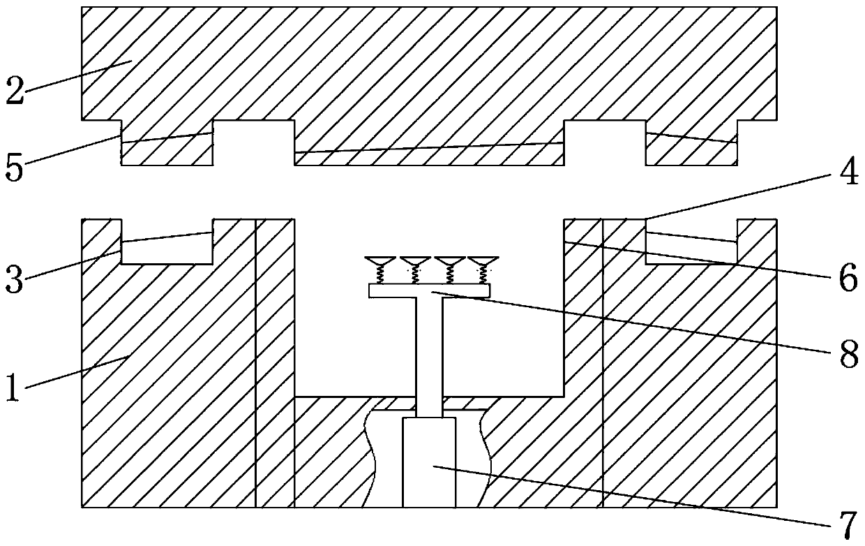
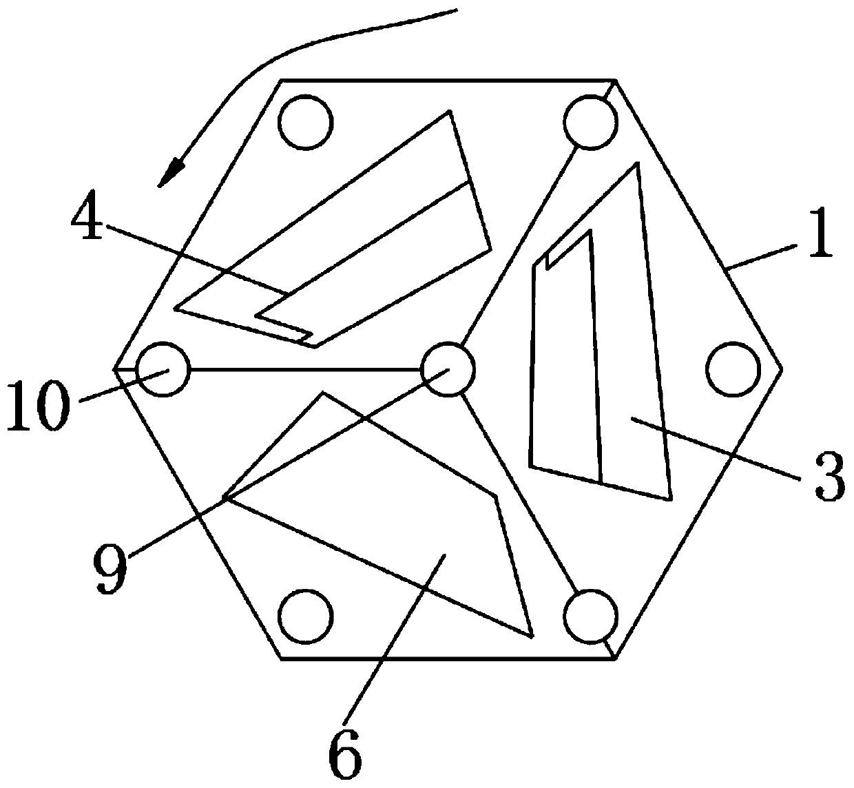
[0026] see Figure 2-6 , including a fixed mold frame 1 and a movable mold frame 2 with a regular hexagonal cross-section. The upper surface of the fixed mold frame 1 is provided with a semi-finished side small insert 3, a finished product side small insert 4 and a removal groove 6, and the semi-finished side The cross-sections of the small insert 3, the small insert 4 on the finished product side, and the take-out groove 6 are rotationally symmetrical with a ...


PUM


Abstract

The invention relates to the technical field of mold equipment, and discloses a vehicle tail lamp injection mold. The vehicle tail lamp injection mold comprises a fixed mold frame and a movable mold frame with regular hexagon type cross sections; a semi-finished product side small insert, a finished product side small insert and a taking-out groove are arranged on the upper surface of the fixed mold frame in sequence; and the cross sections of the semi-finished product side small insert, the finished product side small insert and the taking-out groove are in rotational symmetry with the rotating angle being 120 degrees. In the vehicle tail lamp injection mold, the cross section adopts the regular hexagon design, so that the mold closing precision is improved, the design and production requirements are reduced, the smaller area is occupied, the manufacturer investment cost is reduced, meanwhile, the damage to finished products during taking out can be prevented, the lamp cover production yield is improved, finally, the moving and waiting time of taking out abrasive tools can be prevented, the production continuity is guaranteed, the waiting time of an injection molding valve is shortened, liquid-state materials not meeting the temperature requirement are reduced, the emptying is reduced, the material utilization rate is increased, and the lamp cover production cost is reduced.

Description

technical field [0001] The invention relates to the technical field of mold equipment, in particular to an injection mold for automobile tail lights. Background technique [0002] see figure 1 , Automobile taillight lampshades are usually two-color, and two-color injection molding is generally used. The molding process is divided into two times. After the first injection is completed, the mold is opened, and the movable mold is rotated 180 degrees. After shrinking, cool down, open the mold again and eject it to complete the molding of the lampshade. [0003] The existing inserts and mold frames are usually rectangular, and the two-color injection molding process needs to be rotated 180 degrees before closing the mold again. The cooperation between the fixed mold and the movable mold, the center consistency of the guide post and the mold frame, and the alignment between the guide post and the mold frame The gap tolerance of the guide sleeve has high design and production re...

Claims


Application Information

Patent Timeline
IPC IPC(8): B29C45/26B29C45/16B29C45/04
CPCB29C45/0441B29C45/1615B29C45/2602B29C45/2681B29L2031/7472
Inventor 不公告发明人
Owner 常州宏创车辆部件有限公司
Why Eureka
Try Eureka