Burner

A technology for burners and gas channels, applied in the direction of burners, gas fuel burners, combustion methods, etc., can solve the problems of heat energy loss, panel wear, unfavorable stove cleaning, etc., achieve enhanced suction, increase gas supply speed, The effect of reducing supply resistance

Pending Publication Date: 2019-08-06
NINGBO FOTILE KITCHEN WARE CO LTD
View PDF1 Cites 1 Cited by
  • Summary
  • Abstract
  • Description
  • Claims
  • Application Information

AI Technical Summary

Problems solved by technology

[0002] The gas burner of the existing household gas stove includes a gas mixing chamber, a fire cover, an injection pipe, etc., wherein the outer fire cover is placed on the gas mixing chamber, and a pot support is set on the outside of the outer fire cover. The existing gas stove is actually used During the process, the pot support is directly in contact with the cooker panel, and the pot is placed on the pot support for heating. On the one hand, the heat energy generated by the gas combustion is not only used to heat the pot, but also a considerable part of the heat energy is directly transferred to the panel through the pot support. It is easy to cause the temperature of the panel to be too high and cause the loss of this part of heat energy, and the pot support is directly in contact with the cooker panel, and it is easy to cause the bottom of the pot support to wear the panel due to mutual collision during the cooking process. In addition, the gas mixing chamber of the burner is also a very important part of the cooker. The function of the gas mixing chamber is to mix the gas, so that the gas and the primary air can be mixed more evenly; at the same time, the secondary air is supplied to the inner ring, and the current mixed gas The one-piece fixed structure of the chamber is not conducive to the cleaning of the cooker, especially the inside of the gas mixing chamber and the inside of the waist-shaped hole. There are more and more complaints from users about the difficulty of cleaning the gas mixing chamber. For example, the patent number is ZL201420072885 (the announcement number is CN2037314112U) The Chinese utility model patent "A Kind of Burner", or the patent No. ZL200610052382.8 (the announcement number is CN1884911A) all disclose such a kind of gas mixing chamber. Ring air supply to supply secondary air, but the effect on reducing the flue gas of the inner ring is still very limited, and it is also necessary to further improve the air supply effect of the air mixing chamber to the inner ring

Method used


Image

  • Burner
  • Burner
  • Burner

Examples


Embodiment Construction

[0025] The present invention will be further described in detail below in conjunction with the accompanying drawings and embodiments.

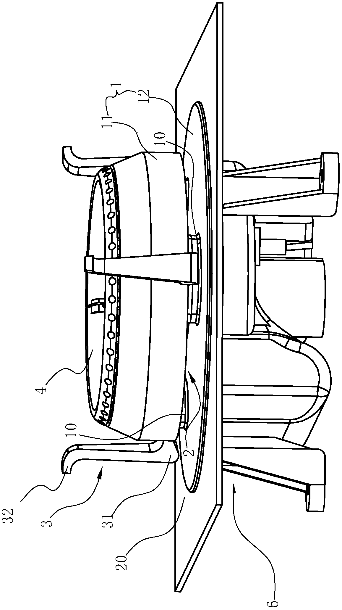
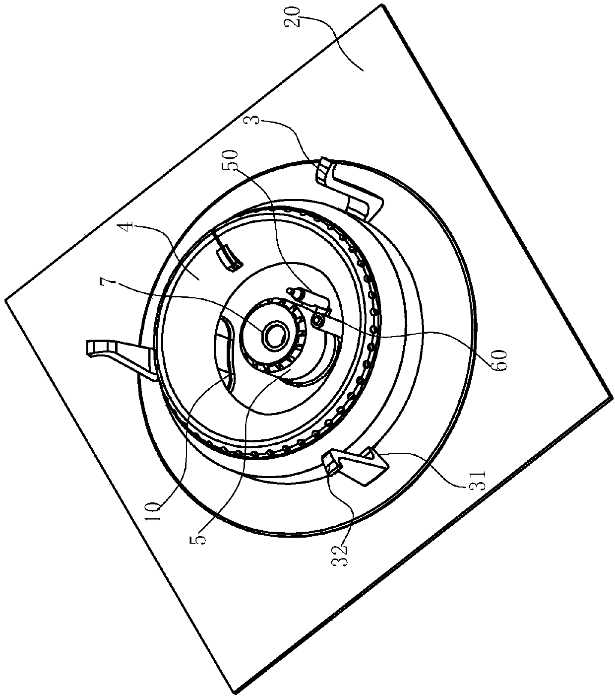
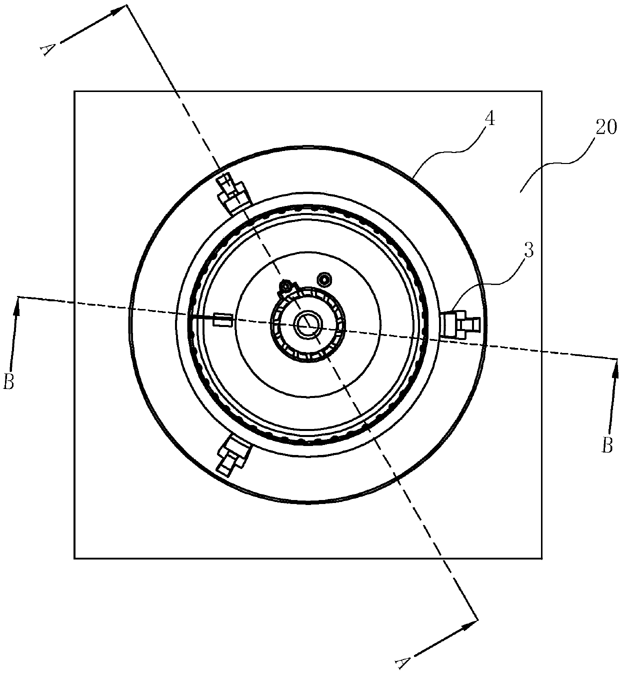
[0026] Such as Figure 1-8Shown is the best embodiment of the present invention, the burner of this embodiment includes a split gas mixing chamber 1, the gas mixing chamber 1 is an outer ring mixing chamber 11 and an inner ring mixing chamber 120, wherein the inner ring The ring gas mixing chamber 120 is composed of a liquid pan 12 located below the outer ring gas mixing chamber. The bottom wall 113 of the outer ring gas mixing chamber 11 is provided with three supporting feet 10, and the outer ring gas mixing chamber 11 is supported on the container through the supporting feet 10 Above the liquid pan 12 and below the outer ring gas mixing chamber 11, a liquid pan 12 for guiding overflow is provided. A through hole 121, the hole wall of the first through hole 121 protrudes upwards to support the inner ring fire cover 5, the hollow part of the...


PUM


Abstract

The invention relates to a burner. The burner includes an outer ring air mixing chamber; the outer ring air mixing chamber includes an inner ring wall surface and an outer ring wall surface which areannular and concentrically disposed at intervals, and a bottom wall connecting the inner ring wall surface and the outer ring wall surface, and the inner ring wall surface and the outer ring wall surface are covered with an outer ring fire cover; and the burner is characterized in that: the outer ring wall surface of the outer ring air mixing chamber is provided with pan supporting legs circumferentially disposed at intervals. Compared with the prior art, the burner is advantageous in that: the pan supporting legs are disposed on the outer ring wall surface of the outer ring air mixing chamber, and so, after the design, the pan supporting legs wholly suspend and are not in contact with a cooker face plate, the wear of the pan supporting legs on the cooker face plate is reduced during a cooking process, the pan supporting legs are not in contact with the cooker face plate, and heat dissipation from the pan supporting legs to the cooker face plate can be reduced.

Description

technical field [0001] The invention relates to the field of gas cookers, in particular to a burner. Background technique [0002] The gas burner of the existing household gas stove includes a gas mixing chamber, a fire cover, an injection pipe, etc., wherein the outer fire cover is placed on the gas mixing chamber, and a pot support is set on the outside of the outer fire cover. The existing gas stove is actually used During the process, the pot support is directly in contact with the cooker panel, and the pot is placed on the pot support for heating. On the one hand, the heat energy generated by the gas combustion is not only used to heat the pot, but also a considerable part of the heat energy is directly transferred to the panel through the pot support. It is easy to cause the temperature of the panel to be too high and cause the loss of this part of heat energy, and the pot support is directly in contact with the cooker panel, and it is easy to cause the bottom of the p...

Claims


Application Information

Patent Timeline
Patent Type & Authority Applications(China)
IPC IPC(8): F23D14/02F23D14/46F23D14/62F24C3/08F24C15/10
CPCF23D14/02F23D14/46F23D14/62F24C3/085F24C15/10
Inventor 戎胡斌邵海忠吴丽波郑军妹徐强
Owner NINGBO FOTILE KITCHEN WARE CO LTD
Why Eureka
Try Eureka