
Double Cyclone Burner

A burner, double cyclone technology, applied in the direction of burner, gas fuel burner, combustion type, etc., can solve the problems of low combustion temperature, gas leakage, gas explosion, etc., to improve safety performance, increase flame temperature, safety sex high effect

Active Publication Date: 2020-04-21
欧华权 +1
View PDF5 Cites 0 Cited by
  • Summary
  • Abstract
  • Description
  • Claims
  • Application Information

AI Technical Summary

Problems solved by technology

[0002] In the current commercial stoves, the burners generally use pre-mixed burners. During the use of pre-mixed burners, air and gas are first mixed in the pipeline, and then they are introduced into the combustion chamber of the burner for combustion. , this mixing method is the traditional pre-mixed type. This pre-mixed burner has two defects. First, the air and gas are mixed unevenly in the pipeline, which will cause the gas to not burn fully and make the combustion temperature relatively high. Low; secondly, this kind of premixed burner is prone to flashback, especially when artificial gas is used, the flame is easy to flow back into the pipeline of the premixing section, and the long-term high temperature tempering is easy to ignite the gas The gas in the pipe will cause serious safety accidents such as gas explosion; in addition, there is no equipment in the existing burner to detect the state of the fire and the combustion state of the burner, and it is easy to open the gas passage when the fire is not ignited, causing Gas leakage; and when the burner is accidentally turned off, the gas pipeline will not be closed, and the gas will continue to flow in, which will cause gas leakage, and an explosion accident will occur after encountering an open flame

Method used


Image

  • Double Cyclone Burner
  • Double Cyclone Burner
  • Double Cyclone Burner

Examples


Embodiment Construction

[0037] The technical solutions in the embodiments of the present invention will be clearly and completely described below in conjunction with the accompanying drawings in the embodiments of the present invention. Obviously, the described embodiments are only a part of the embodiments of the present invention, rather than all the embodiments. Based on the embodiments of the present invention, all other embodiments obtained by those of ordinary skill in the art without creative work shall fall within the protection scope of the present invention.

[0038] The purpose of the present invention is to provide a dual cyclone burner to solve the problems existing in the prior art.

[0039] In order to make the above objectives, features and advantages of the present invention more obvious and understandable, the present invention will be further described in detail below with reference to the accompanying drawings and specific embodiments.

[0040] This embodiment provides a dual cyclone bur...


PUM


Abstract

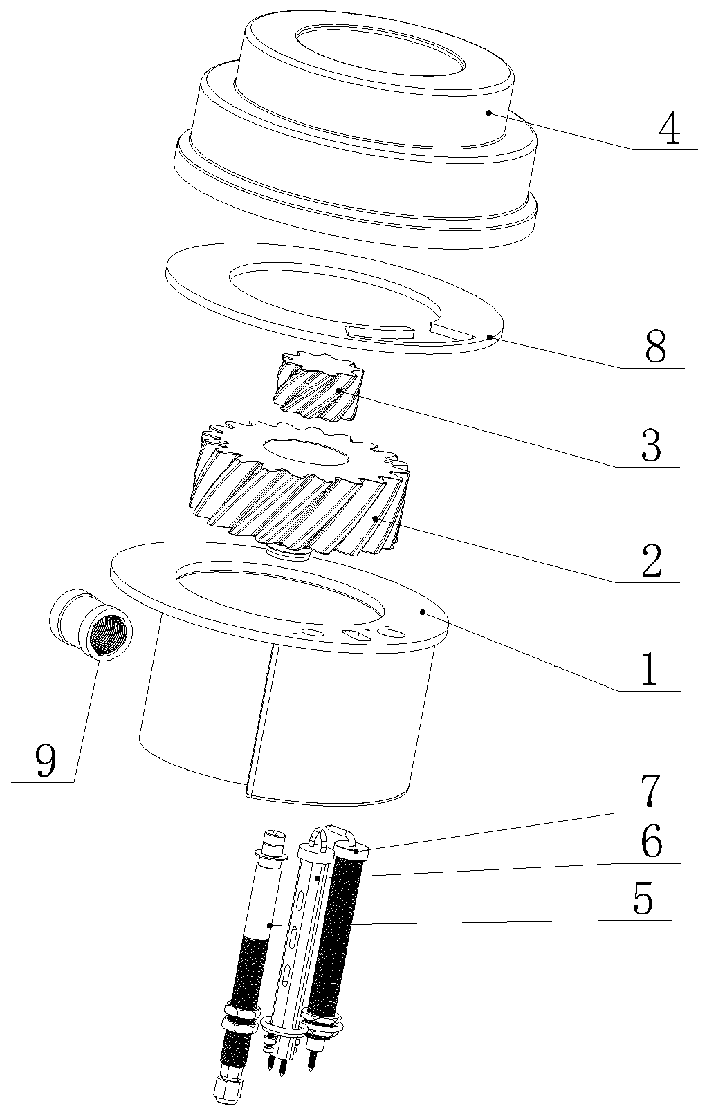
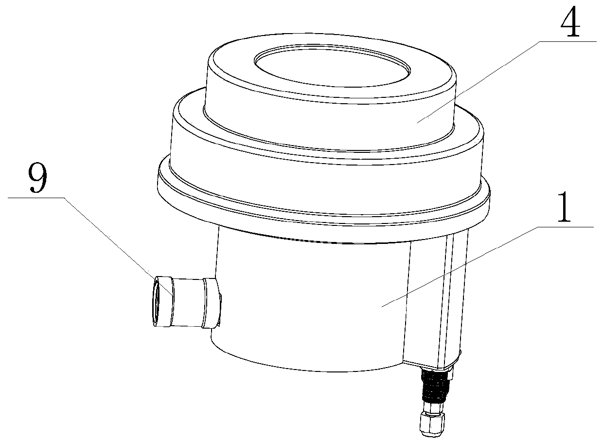
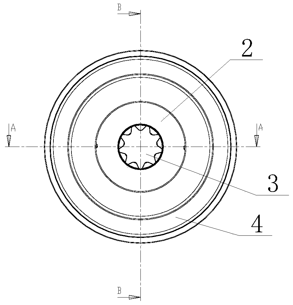
The invention discloses a double cyclone burner comprising a burner air box, an outer ring burning core, an inner ring burning core, a kindling burner, an ignition pin and a flame induction pin. The outer ring burning core is arranged in a holding cavity of the burner air box. A plurality of outer helical teeth are distributed outside the outer ring burning core circumferentially. The outer helical teeth and the inner wall of the burner air box form a plurality of outer helical air channels. Each outer helical air channel is provided with a fuel gas outlet discharging fuel gas. The inner ringburning core is arranged in a holding groove formed in a core body of the outer ring burning core from top to bottom. A plurality of inner helical teeth are distributed outside the inner ring burningcore circumferentially. The inner helical teeth and the groove wall of the holding groove form a plurality of inner helical air channels. Each inner helical air channel is provided with a fuel gas outlet discharging fuel gas. An air inlet in the bottom of the burner air box communicates with the outer helical air channels and the inner helical air channels. Through the double cyclone burner provided by the invention, fuel gas can be fully burnt, flame temperature is increased, and use safety is ensured.

Description

Technical field [0001] The invention relates to the technical field of stoves, in particular to a double cyclone burner. Background technique [0002] In the current commercial stoves, the burners generally use premixed burners. During the use of premixed burners, air and gas are first mixed in the pipeline, and then are introduced into the burner combustion chamber for combustion. This mixing method is a traditional pre-mixing type. This pre-mixing burner has two disadvantages. First, the uneven mixing of air and gas in the pipeline will cause the gas to not be fully combusted and the combustion temperature will be higher. Low; secondly, this kind of pre-mixed burner is prone to backfire, especially when using artificial gas, the flame is easy to return to the pipeline of the pre-mixing section, long-term high-temperature tempering, easy to ignite the gas The gas in the pipe will cause serious safety accidents such as gas explosion. In addition, there is no equipment for detect...

Claims


Application Information

Patent Timeline
Patent Type & Authority Patents(China)
IPC IPC(8): F23D14/02F23D14/46F23D14/62
CPCF23D14/02F23D14/46F23D14/62F23D2900/14062
Inventor 欧华权郑伟燊
Owner 欧华权
Learn More