Noise reduction type extractor hood

A range hood and noise reduction technology, which is applied in the direction of removing oil fumes, mechanical equipment, machines/engines, etc., can solve problems such as inability to reduce noise, and achieve good noise reduction and noise reduction effects

Pending Publication Date: 2019-08-06
NINGBO FOTILE KITCHEN WARE CO LTD
View PDF2 Cites 2 Cited by
  • Summary
  • Abstract
  • Description
  • Claims
  • Application Information

AI Technical Summary

Problems solved by technology

However, during the acceleration process of the airflow, due to the change of its speed, the frequency of the noise it produces also changes, and the above-mentioned patent does not have a good noise reduction effect on the changing sound frequency.

Method used


Image

  • Noise reduction type extractor hood
  • Noise reduction type extractor hood
  • Noise reduction type extractor hood

Examples


Embodiment 1

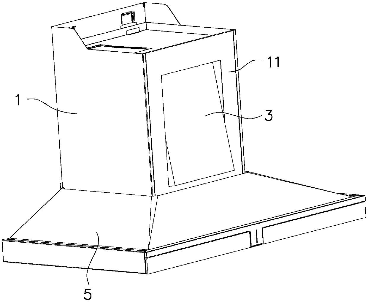
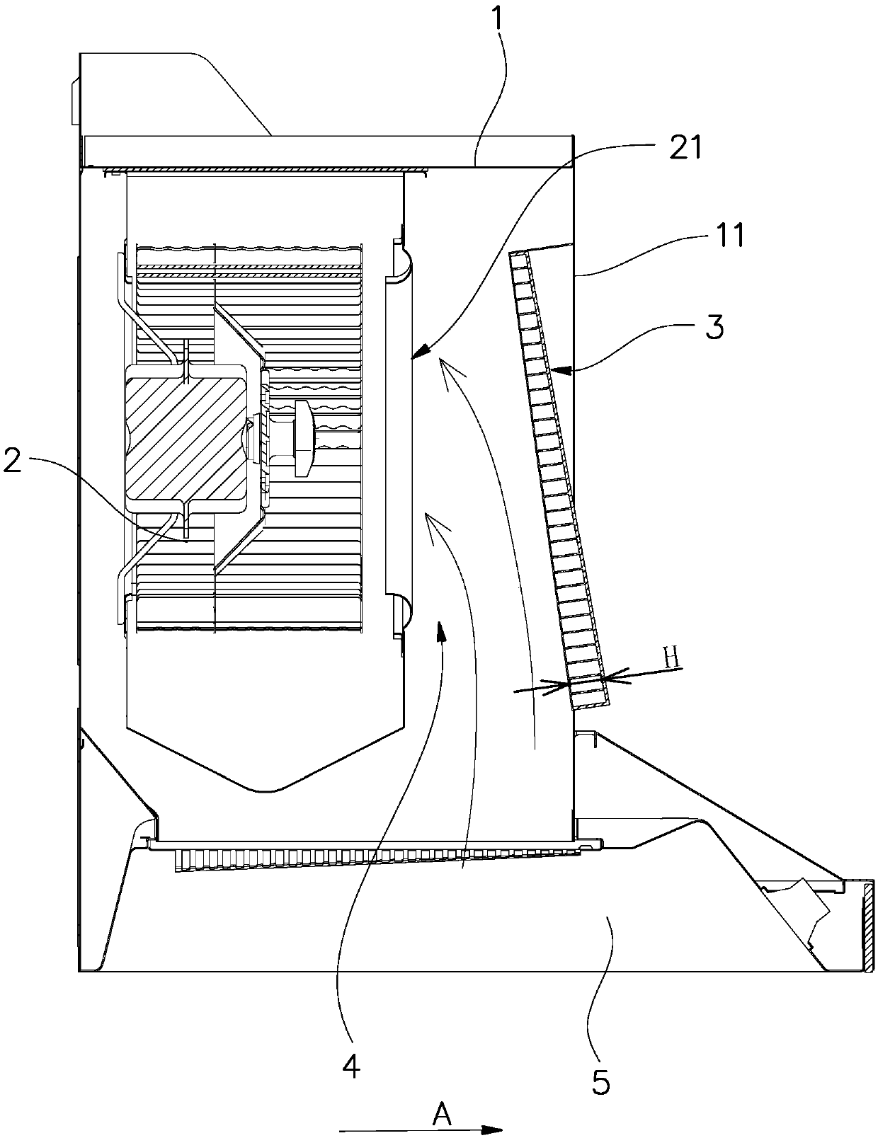
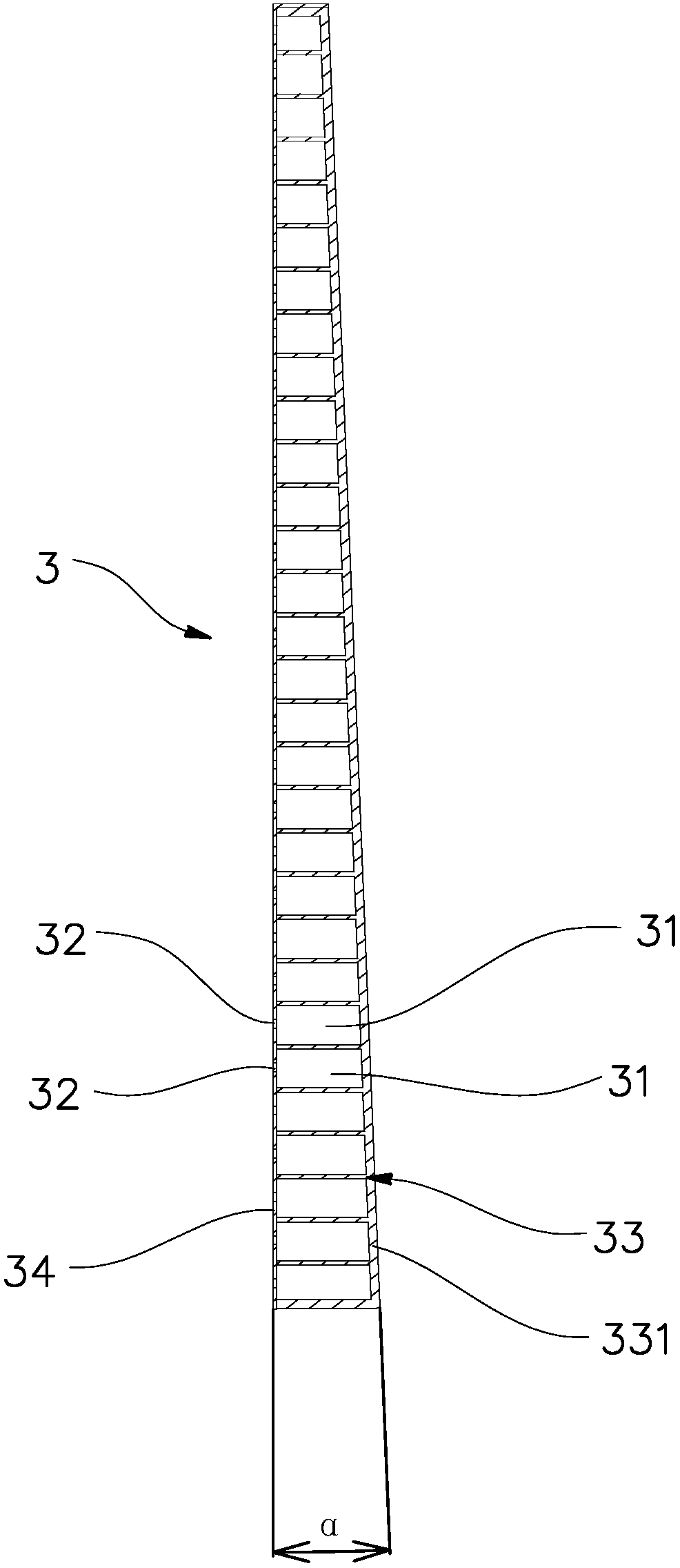
[0029] like Figure 1 to Figure 5 shown, with figure 2 The direction shown by the middle arrow A is forward. The noise reduction type range hood in this embodiment includes a fan frame 1, a fan 2 is installed inside the fan frame 1, a fume collecting hood 5 is installed under the fan frame 1, and the fan 2 has a fan air inlet 21 on the front side, the fume collecting hood 5 has an air inlet that communicates with the fan air inlet 21, and a noise reduction device 3 is installed on the front cover 11 of the fan frame 1, and the noise reduction device 3 Facing the air inlet 21 of the fan, the noise reduction device 3 includes a grid plate 33 closed on the front side and a micro-porous plate 34 arranged on the rear side of the grid plate. The micro-orifice plate 34 is facing the air inlet 21 of the fan, and the micro-orifice plate 34 is inclined forward from top to bottom. Since the end face of the air inlet 21 of the fan is located on the vertical plane, the noise reduction de...

Embodiment 2

[0034] like Image 6 and Figure 7 As shown, the depth of the noise reduction cavity 31 of the noise reduction device 3 of this embodiment remains unchanged in the vertical direction, and the cross-section of the noise reduction cavity 31 gradually decreases from bottom to top, so as to satisfy the noise reduction hole area S The ratio S / V to the corresponding noise reduction cavity volume V gradually increases from bottom to top. The rest of the structure of this embodiment is the same as that of the first embodiment, and will not be described here.

Embodiment 3

[0036] like Figure 8 As shown, the area S of the noise reduction cavity of the noise reduction device 3 in this embodiment gradually increases from bottom to top, and the volume V of the noise reduction cavity remains unchanged in the vertical direction, so that the area S of the noise reduction hole and the corresponding The ratio S / V of the volume V of the noise reduction cavity gradually increases from bottom to top. The rest of the structure of this embodiment is the same as that of the first embodiment, and will not be described here.


PUM


Abstract

A noise reduction type extractor hood includes a fan frame and a fan disposed in the fan frame; a noise reduction device is installed on a cover plate at a position directly facing an air inlet of thefan; and the extractor hood is characterized in that: an air inlet passage which is gradually narrowed from bottom to top is formed between the noise reduction device and the air inlet of the fan, the noise reduction device is provided with noise reduction cavities and noise reduction holes corresponding to the noise reduction cavities, the noise reduction cavities are arranged up and down in order, the noise reduction holes are disposed on the side surface of the noise reduction device opposite to the air inlet of the fan, and the ratio S / V of the area S of the noise reduction holes to the volume V of the corresponding noise reduction cavities gradually increases from bottom to top. The air inlet passage which is gradually narrowed from bottom to top is formed between the noise reductiondevice of the noise reduction type extractor hood and the air inlet of the fan, the ratio S / V of the area S of the noise reduction holes to the volume V of the corresponding noise reduction cavitiesgradually increases from bottom to top, and a Helmholtz resonance noise elimination principle is utilized, so that the resonance frequency of the noise reduction device is matched with the airflow noise frequency located at a corresponding horizontal plane, and noise reduction and noise elimination effects are good.

Description

technical field [0001] The invention relates to a range hood, in particular to a noise reduction type range hood. Background technique [0002] Chinese cooking will produce a lot of oil fumes. In order to keep the kitchen environment clean and human health, range hoods have become one of the essential equipment in modern home kitchens. During the operation of the range hood, the airflow movement produces turbulent flow and makes noise, which affects people's cooking experience and physical health. In order to reduce the noise of range hoods, people have invented various range hoods with noise reduction structures, such as "A Quiet Type" disclosed in Chinese invention patent No. 201310627547.X (authorized announcement No. CN 103697512 B). Range hood", the range hood is provided with a sound-absorbing shroud at the position facing the front air inlet of the volute, and micro-holes are arranged on the sound-absorbing shroud, and the sound-absorbing shroud is tilted to the rear...

Claims


Application Information

Patent Timeline
IPC IPC(8): F24C15/20F04D29/66
CPCF04D29/663F24C15/20
Inventor 袁柯铭施旭娜
Owner NINGBO FOTILE KITCHEN WARE CO LTD
Why Eureka
Try Eureka