Noise reduction structure and noise reduction method of high-speed and high-pressure centrifugal blower

A centrifugal blower, high-speed technology, used in mechanical equipment, machines/engines, liquid fuel engines, etc., can solve the problems of low noise reduction coefficient, high-frequency aerodynamic noise, complex structure, etc. The effect of length, good noise reduction and noise reduction

Pending Publication Date: 2021-12-10
湖南泛航智能装备有限公司
View PDF6 Cites 2 Cited by
  • Summary
  • Abstract
  • Description
  • Claims
  • Application Information

AI Technical Summary

Problems solved by technology

The structure adopted by the above-mentioned noise reduction device is relatively complicated, and the materials used are mainly sound-proof cotton (rubber board, foam rubber board, damping board, etc.), sound-absorbing cotton (polyester fiber, centrifugal glass wool, rock wool, mineral wool, Plant fibers, etc.) and porous sound-insulating materials (such as galvanized mesh panels, stainless steel mesh panels, etc.), these materials have relatively low noise reduction coefficients (not greater than 0.8)
Therefore, it is difficult for existing noise reduction devices to solve and eliminate the problem of high-frequency aerodynamic noise. In view of this, noise reduction of high-speed and high-pressure blowers is a key technical problem to be solved urgently

Method used


Image

  • Noise reduction structure and noise reduction method of high-speed and high-pressure centrifugal blower
  • Noise reduction structure and noise reduction method of high-speed and high-pressure centrifugal blower
  • Noise reduction structure and noise reduction method of high-speed and high-pressure centrifugal blower

Examples


Embodiment Construction

[0024] In order to make the object, technical solution and advantages of the present invention clearer, the present invention will be described in further detail below with reference to the accompanying drawings and preferred embodiments. However, it should be noted that many of the details listed in the specification are only for readers to have a thorough understanding of one or more aspects of the present invention, and these aspects of the present invention can be implemented even without these specific details.

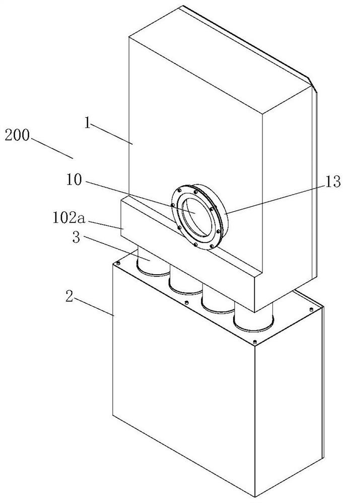
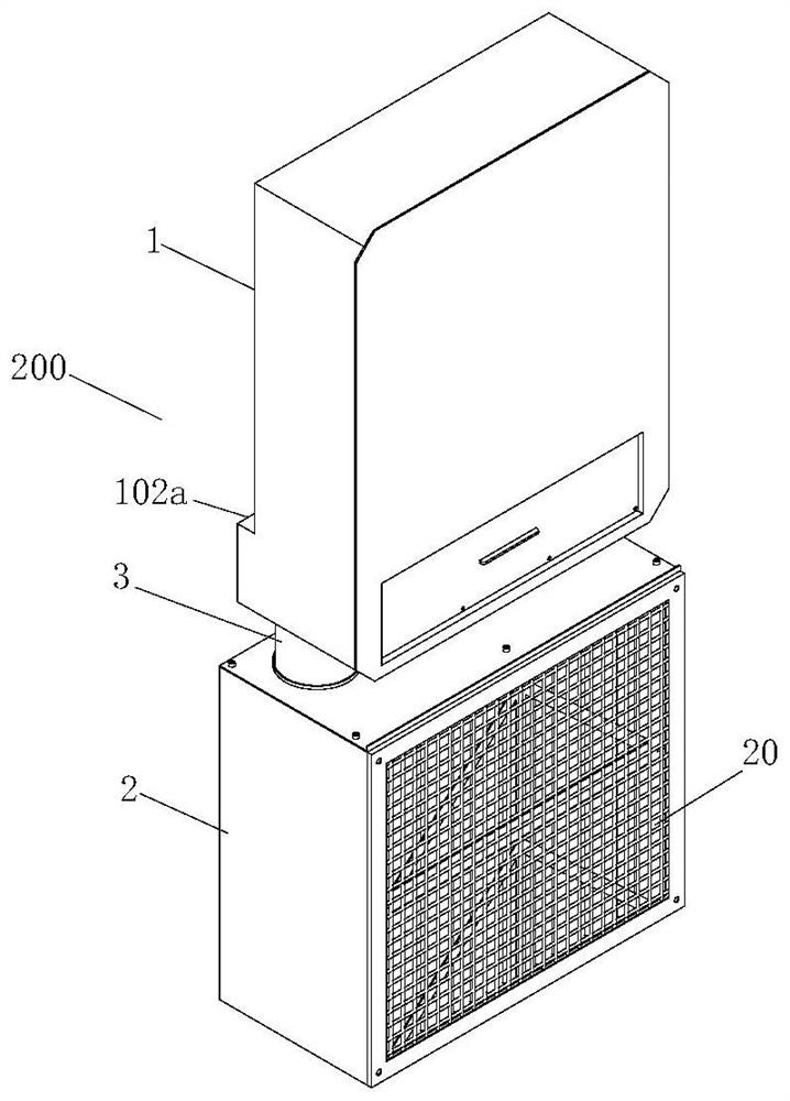
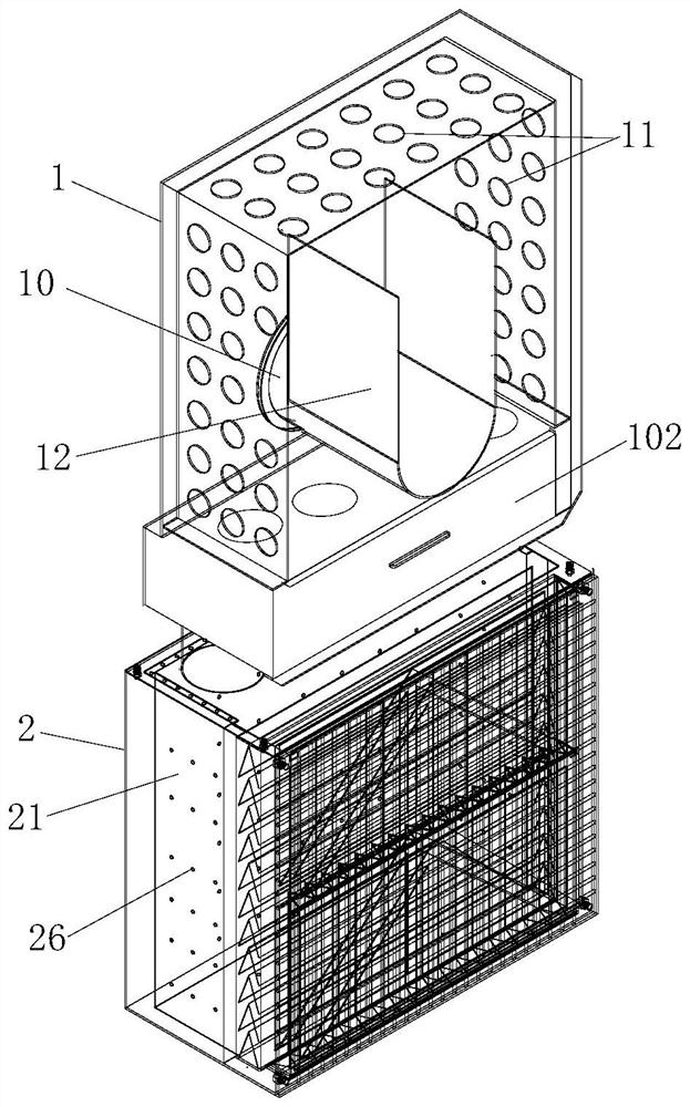
[0025] combine figure 1 , figure 2 , image 3 with Figure 4As shown, according to a noise reduction structure of a high-speed and high-pressure centrifugal blower of the present invention, the noise reduction structure includes a noise reduction box body 200, and the noise reduction box body 200 includes an upper box body 1, a lower box body 2 and a connecting air cylinder 3 , the number of the connecting air cylinder 3 is 1 or more, the number of the connec...


PUM


Abstract

The invention discloses a noise reduction structure and noise reduction method of a high-speed and high-pressure centrifugal blower. The noise reduction structure comprises an upper box body, a lower box body and a connecting air duct, the bottom end of the upper box body is vertically connected to the top end of the lower box body through the connecting air duct, an air outlet is formed in the front side of the upper box body, and an air inlet is formed in the rear side of the lower box body. A resonant cavity, an air outlet noise reduction cavity, a first filter plate and multiple layers of noise reduction channel plates are arranged in the lower box body, the first filter plate and the noise reduction channel plates are sequentially arranged in the resonant cavity between the air inlet and the air outlet noise reduction cavity, and 1/4 wavelength pipes are installed on the left side wall, the right side wall and the top in the upper box body. Flow guide plates are arranged on the inner wall of the front side of the upper box body and along the periphery of the air outlet. According to the noise reduction structure and the noise reduction method, the flowing path of high-speed air flow from the lower box body to the upper box body is gradually weakened, and in the high-speed flowing process of high-speed air, the length of a silencing pipeline is increased; and meanwhile, the flow speed of the air is strictly controlled in the resonant cavity, and the good restraining, silencing and noise reduction effect can be achieved.

Description

technical field [0001] The invention belongs to the technical field of high-speed and high-pressure blower noise reduction, in particular to the technical field of blower noise reduction and noise reduction, in particular to a high-speed, high-pressure centrifugal blower noise reduction structure and a noise reduction method thereof. Background technique [0002] The high-frequency aerodynamic noise generated by high-speed and high-pressure blowers during high-speed operation is relatively large, and the noise needs to be reduced to a reasonable range. The device itself is relatively large in size and takes up a lot of space, which has a great impact on the performance of the blower machine. At present, the devices for controlling equipment noise include shock absorption and noise reduction, sound absorption and noise reduction, sound insulation and noise reduction, and comprehensive noise reduction. Vibration and noise reduction technology is to study vibration isolation a...

Claims


Application Information

Patent Timeline
Patent Type & Authority Applications(China)
IPC IPC(8): F04D29/66F04D29/70
CPCF04D29/664F04D29/665F04D29/667F04D29/703
Inventor 桂云峰张勇杨崎峰杜海英李毅
Owner 湖南泛航智能装备有限公司
Why Eureka
Try Eureka