
Experimental device and experimental method used for studying rock stress distribution by using magnetic fluid

A technology of rock stress and experimental device, used in measurement devices, hydraulic/pneumatic measurement, analysis of materials, etc.

Active Publication Date: 2019-08-06
CHINA THREE GORGES UNIV
View PDF5 Cites 4 Cited by
  • Summary
  • Abstract
  • Description
  • Claims
  • Application Information

AI Technical Summary

Problems solved by technology

At present, no research in this area has been carried out in the field of rock stress

Method used


Image

  • Experimental device and experimental method used for studying rock stress distribution by using magnetic fluid
  • Experimental device and experimental method used for studying rock stress distribution by using magnetic fluid
  • Experimental device and experimental method used for studying rock stress distribution by using magnetic fluid

Examples


Embodiment 1

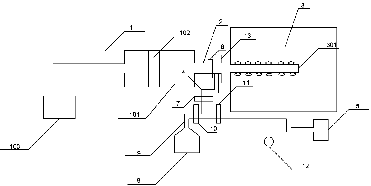
[0028] Embodiment 1: as figure 1 Among them, an experimental device for using magnetic fluid to study rock stress distribution, including a pressing device 1, the outlet of the pressing device 1 is connected to the injection pipe 2, the injection pipe 2 is inserted into the borehole 301 of the sample 3, and the injection pipe 2 is connected to the vacuum pump 5 through the suction pipe 4, the injection pipe 2 is provided with a first valve 6, and the suction pipe 4 is provided with a second valve 7.

[0029] Specifically, the pressing device 1 includes an injection cavity 101 , and a piston 102 is arranged in the injection cavity 101 , and the end of the injection cavity 101 away from the injection tube 2 is connected to a pressure pump 103 through a pipeline.

[0030] The pressure pump 103 can be a hand-held or desktop pressure pump. In this embodiment, a desktop pressure pump is preferred, which can ensure the constant pressure of the pushing material.

[0031] The pipeline...

Embodiment 2

[0058] Embodiment 2: Different from Embodiment 1, in step five, metal powder or magnetic powder is added in the borehole 301. Since the magnetic fluid in the rock pores has magnetism, the metal powder will accumulate on the surface of the hole wall of the rock borehole. Then use a micro-camera to take 3D pictures of the internal images of the borehole to establish a three-dimensional model of the borehole accumulation. The amount of metal powder accumulated on the surface of the wall of the rock borehole reflects the amount of magnetic fluid pressed into the rock pores, and then can be used for analysis. The stress distribution of the rock stress is observed in a straight pipe.

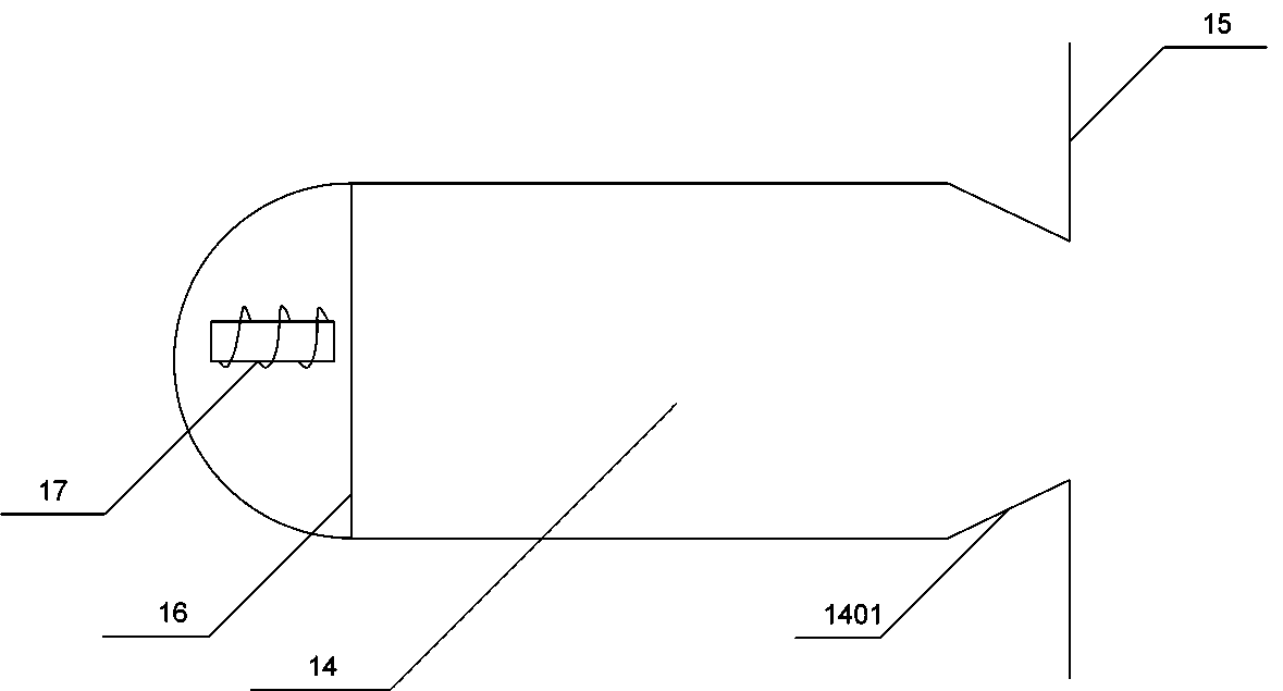
[0059] In step 6, after the measurement is completed, the recovery port 1401 of the recovery chamber 14 of the recovery device is attached to the outside of the borehole 301, and the electromagnet 17 is powered on to recover the magnetic fluid and metal powder in the borehole 301.


PUM


Abstract

The invention provides an experimental device used for studying rock stress distribution by using a magnetic fluid. A discharge port of a material pressing device is connected to an injection pipe. The injection pipe is connected to a drilling hole of a sample. The injection pipe is connected to a vacuum pump through a suction pipe. The injection pipe is provided with a first valve and the suctionpipe is provided with a second valve. The invention also provides an experimental method used for studying the rock stress distribution by using the magnetic fluid. The method comprises the followingsteps of step1, measuring a porosity of the sample; step2, drilling a hole in the middle of the sample, and carrying out a loading experiment on the sample; step3, vacuumizing the drilling hole and pressing the magnetic fluid into the drilling hole through the material pressing device; step4, cleaning the magnetic fluid in the drilling hole; step5, detecting magnetic field intensity in the drilling hole; and step6, loading different loading forces and measuring the magnetic field intensities under the different loading forces. The experimental device can press the magnetic fluid into the holes of the rock, a test platform is built for studying a relationship between a rock stress and a magnetic fluid pressing amount and a corresponding test method is provided.

Description

technical field [0001] The invention belongs to the field of rock stress research, in particular to an experimental device and an experimental method for using magnetic fluid to study rock stress distribution. Background technique [0002] At present, there are few rock stress testing methods and they have great limitations. The widely used in-situ stress measurement method is the stress relief method. The basic principle is that when the micro-element of the rock mass with the measuring element fixed is separated from the bedrock artificially. Its geometry will undergo elastic recovery. The relationship between recovery strain and stress field can be established by using elastic theory and rock elastic constant. This method has complex experimental equipment, high requirements on the experimental environment, high energy consumption, and usually causes damage to the original rock body. Due to the inconvenience of operation, this method has great limitations. [0003] Fe...

Claims


Application Information

Patent Timeline
Patent Type & Authority Applications(China)
IPC IPC(8): G01L1/02G01N15/08
CPCG01L1/02G01N15/088G01N2015/0813
Inventor 杨渝南谢晓康占星王子明刘杰李洪亚唐洪宇高素芳张瀚李远航何卓文孙涛黎照
Owner CHINA THREE GORGES UNIV
Learn More