An optoelectronic device frequency response testing system and method

A technology for frequency response testing and optoelectronic devices, applied in electromagnetic wave transmission systems, electrical components, transmission systems, etc., can solve problems such as insufficient dynamic range of light source modules, achieve widening of the dynamic range of light output, simple and fast operation, and improve accuracy Effect

Active Publication Date: 2020-08-11
CHINA ELECTRONIS TECH INSTR CO LTD
View PDF6 Cites 0 Cited by
  • Summary
  • Abstract
  • Description
  • Claims
  • Application Information

AI Technical Summary

Problems solved by technology

[0005] In order to solve the deficiencies in the prior art, the present disclosure provides a frequency response testing system and method for optoelectronic devices, which solves the problem of insufficient dynamic range of the light

Method used


Image

  • An optoelectronic device frequency response testing system and method
  • An optoelectronic device frequency response testing system and method
  • An optoelectronic device frequency response testing system and method

Examples


Embodiment 1

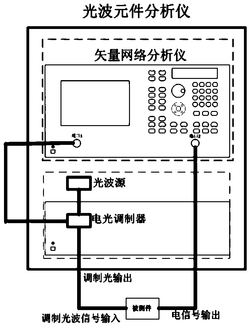
[0044] The optical signal component analyzer is one of the common methods for measuring the frequency response parameters of the photoelectric conversion module. It can realize the modulation of the continuous light by the radio frequency signal internally. By adjusting the optical power of the optical light source module, the frequency of the photoelectric conversion module under different optical power can be realized. Response measurement, the test system composed of external adjustable optical attenuator can adjust the attenuation value of the attenuator in real time during the test process, and can also realize the frequency response measurement of the photoelectric conversion module under different optical power. The two methods are currently the main The measurement method, the optical signal component analyzer method adopts an integrated desktop measurement scheme, its principle is based on the vector network analyzer to realize the transmission and reception of microwav...

Embodiment 2

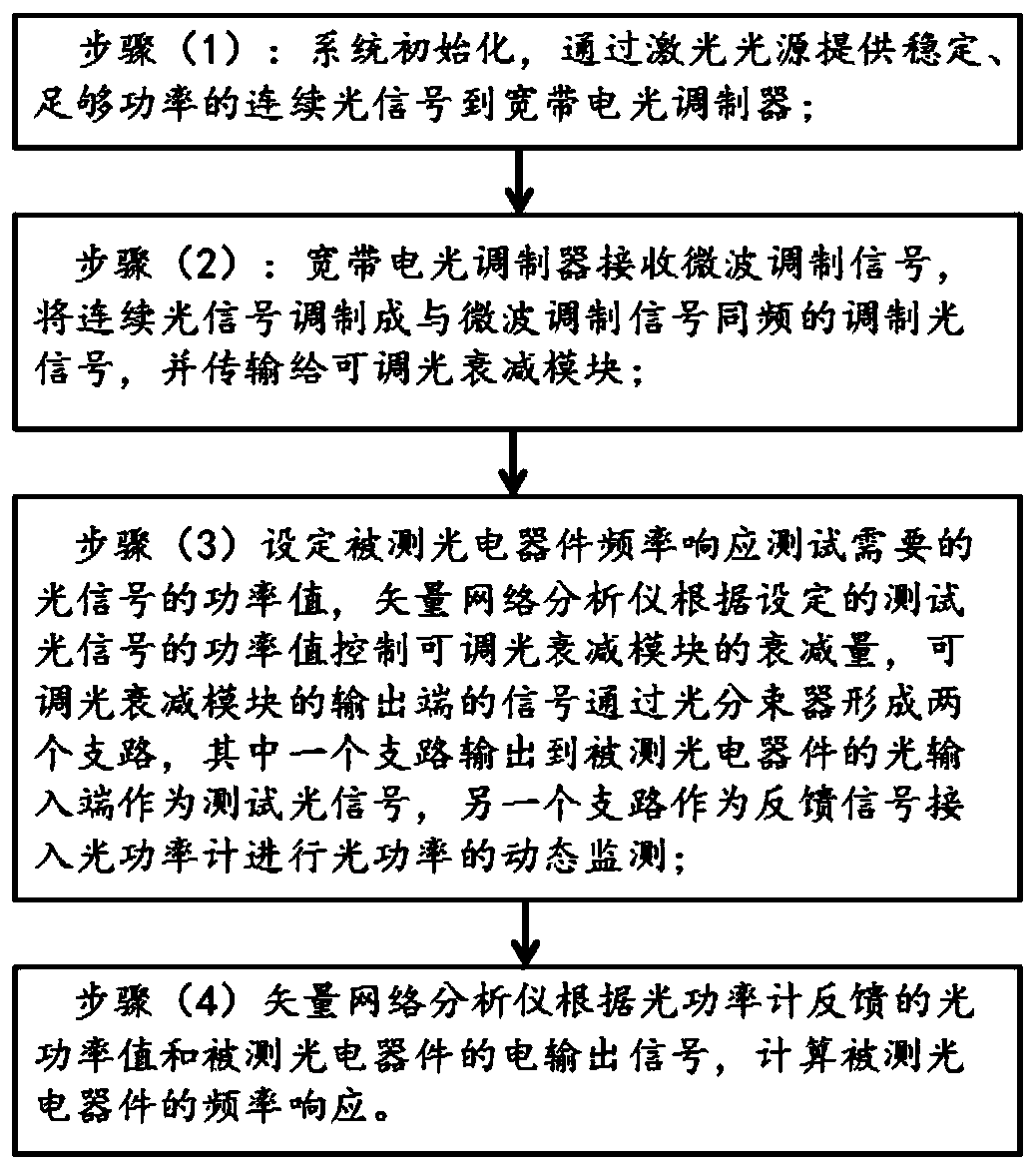
[0056] Such as image 3 and 4 As shown, Embodiment 2 of the present disclosure provides a method for testing the frequency response of an optoelectronic device, and the steps are as follows:

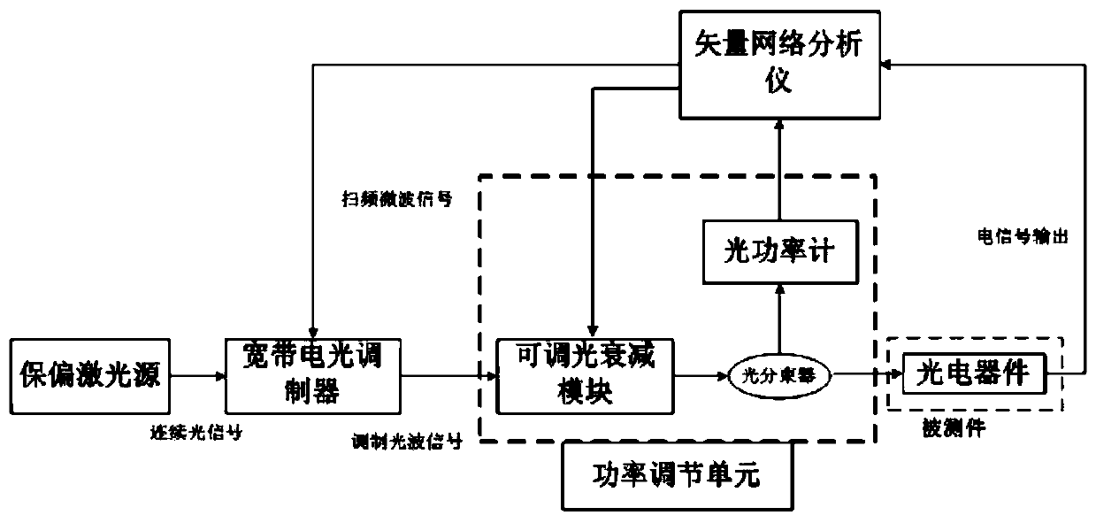
[0057] (1) System initialization, providing a stable, continuous optical signal with sufficient power to the broadband electro-optic modulator through the laser light source;

[0058] (2) The broadband electro-optic modulator receives the microwave modulation signal, modulates the continuous optical signal into a modulated optical signal with the same frequency as the microwave modulation signal, and transmits it to the adjustable optical attenuation module;

[0059] (3) Set the power value of the optical signal required for the frequency response test of the optoelectronic device under test, and the vector network analyzer controls the attenuation of the adjustable optical attenuation module according to the set power value of the test optical signal, and the adjustable optical attenua...


PUM


Abstract

The invention provides a photoelectric device frequency response test system and method. The photoelectric device frequency response test system comprises a laser light source, a broadband electro-optical modulator, a power adjusting module and a vector network analyzer. The laser light source provides a stable continuous optical signal for the broadband electro-optical modulator; the power adjusting module is used for receiving the modulated optical signal output by the broadband electro-optical modulator and outputting optical signals with different powers to the tested optical and electrical device according to the control signal of the vector network analyzer; the vector network analyzer is used for providing a microwave modulation signal and a control signal of the power adjusting module, receiving an electric output signal output by the photometric electric device and a power-regulated optical signal fed back by the power regulation module, and calculating the frequency responseof the to-be-measured optical electrical device under different power optical signals. The problem that the dynamic range of the light source module is insufficient is solved, large dynamic power adjustment can be achieved, the problem that an electro-optical modulator scans again and finds a working point when the optical power is adjusted can be avoided, and the testing efficiency is greatly improved.

Description

technical field [0001] The present disclosure relates to the field of frequency response testing, in particular to a frequency response testing system and method for optoelectronic devices. Background technique [0002] The statements in this section merely provide background information related to the present disclosure and may not necessarily constitute prior art. [0003] The broadband electro-optical modulation module mainly completes the modulation of continuous light by radio frequency signals, and then realizes the test of the frequency response characteristics of optoelectronic devices. It is an important part of the optical receiver of the optical fiber communication system and the frequency response parameter test of optoelectronic devices. The optoelectronic device under test modulates optical signals at different powers, and the frequency response is different. Therefore, the electro-optic modulation module needs to provide modulated optical signals with differen...

Claims


Application Information

Patent Timeline
IPC IPC(8): H04B10/079
CPCH04B10/07953H04B10/07955
Inventor 金辉张爱国曲天阳鞠军委徐桂城韩顺利张志辉闫继送
Owner CHINA ELECTRONIS TECH INSTR CO LTD
Why Eureka
Try Eureka