
Stalk pulling and clamping conveying device of cotton stalk pulling crusher

A clamping conveying and pulverizer technology, which is applied in the direction of picking machines, harvesters, agricultural machinery and implements, etc., can solve the problems of heavy machine cost, large conveying resistance, and easy blockage

Pending Publication Date: 2019-08-09
XINJIANG AGRI UNIV
View PDF0 Cites 4 Cited by
  • Summary
  • Abstract
  • Description
  • Claims
  • Application Information

AI Technical Summary

Problems solved by technology

[0004] The straw conveying device of the existing cotton straw crushing operation machine mostly adopts flat belt conveying or conveying chain conveying, the grasping ability for the straw is not strong, and it is easy to be blocked during the conveying process, the conveying resistance is large, and the conveying volume is small. The middle straw is easy to loose and fall, which is not conducive to the subsequent crushing and returning of the straw, which reduces the working efficiency of the operation, and needs to be equipped with various transmission devices and tensioning devices. The machine is relatively heavy and the cost is too high
[0005] The straw conveying device of the existing cotton straw crushing machine is not strong in conveying capacity, it is prone to blockage during conveying, the conveying resistance is large, the conveying capacity is small, the ability to grasp straw is not strong, and the straw is easy to loose during conveying Falling is not conducive to the subsequent crushing of straw

Method used


Image

  • Stalk pulling and clamping conveying device of cotton stalk pulling crusher
  • Stalk pulling and clamping conveying device of cotton stalk pulling crusher
  • Stalk pulling and clamping conveying device of cotton stalk pulling crusher

Examples


Embodiment Construction

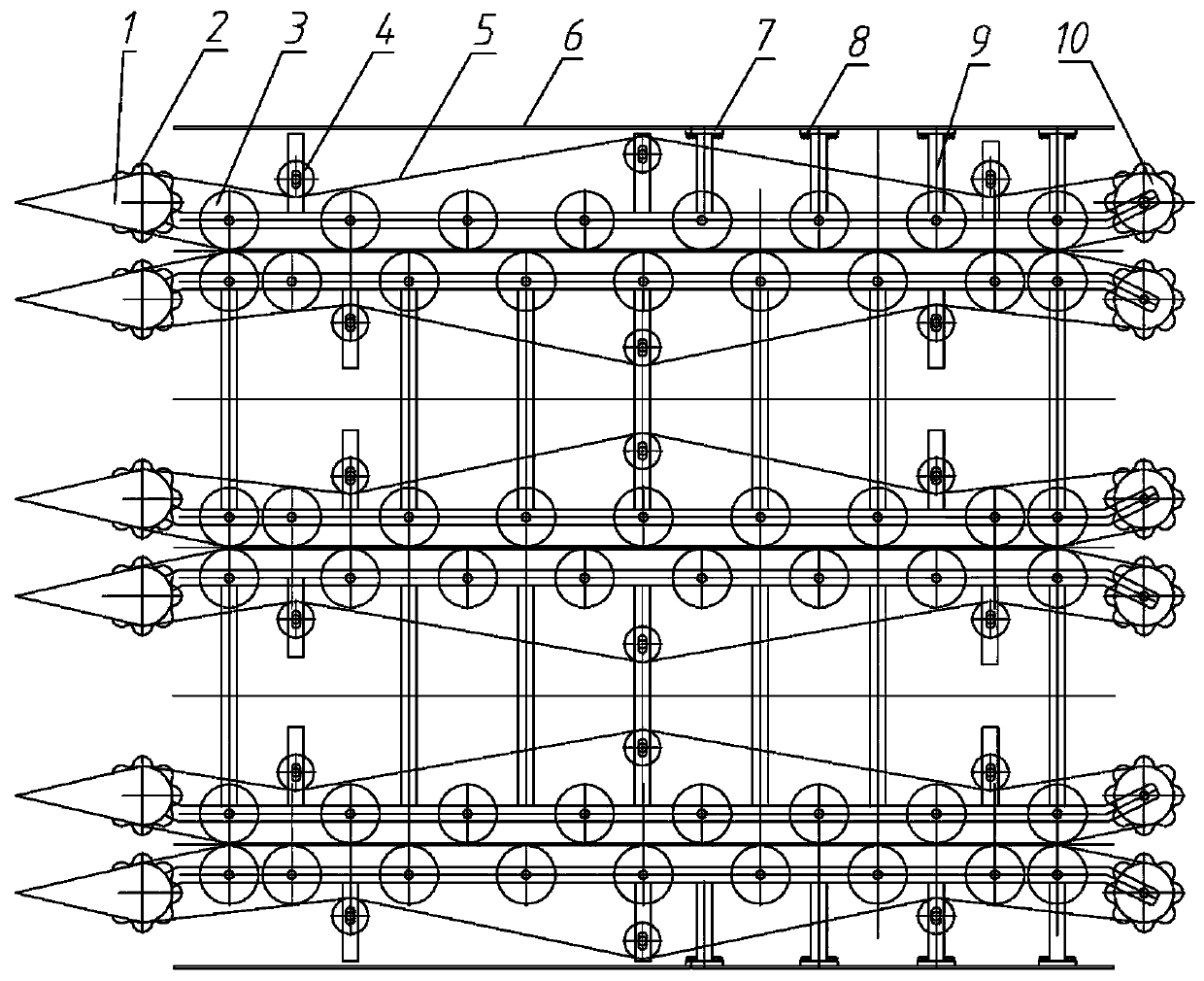
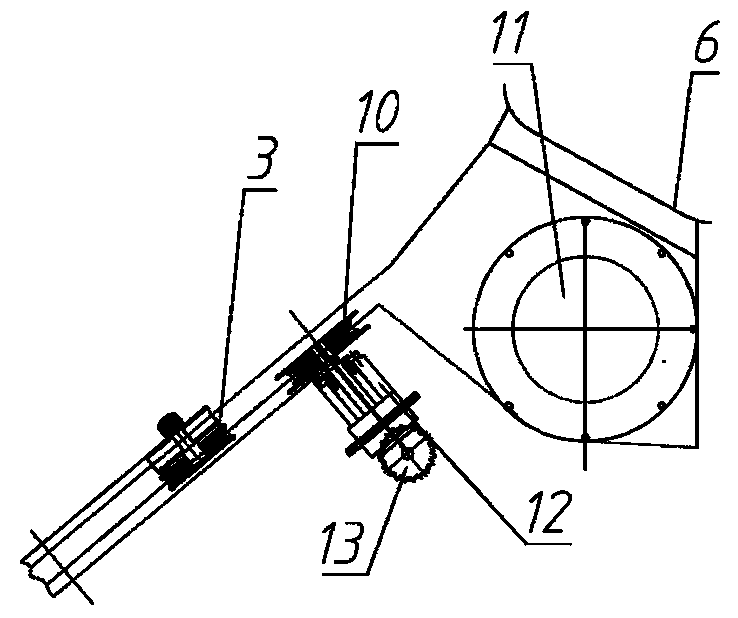
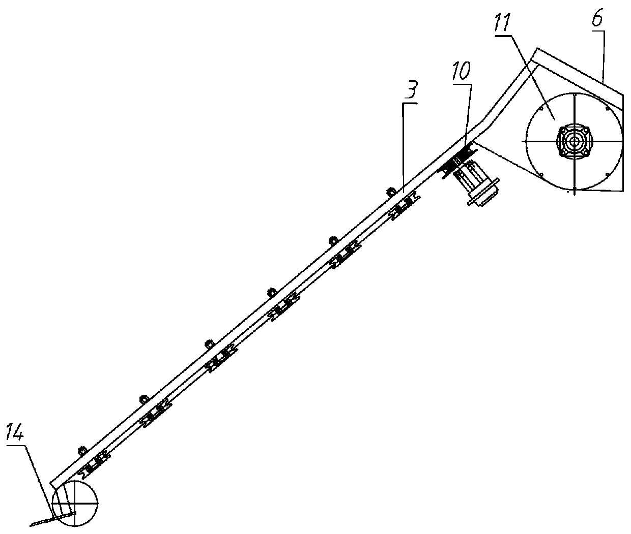
[0014] A stalk pulling and clamping conveying device of a cotton stalk grinder, such as Figure 1 to Figure 4 Shown, comprise the frame 6 of oblique arrangement, the frame 6 lower end is provided with film lifting shovel 14, and front clamping conveying mechanism is arranged side by side on the frame, and each clamping conveying mechanism all comprises crop divider 1, bottom Guide wheel 2, belt pulley 3, tension pulley 4, V-belt 5 and top guide wheel 10 located at the top of the frame, the top of the frame is provided with an auger conveying roller 11, and the bottom of the top guide wheel shaft is respectively provided with a transmission box 12 and The transmission sprocket 13, the transmission sprocket 13 is connected with the external power input mechanism, the bottom guide wheel 2, the pulley 3 and the top guide wheel 10 are all driven to rotate by the transmission box 12 and the V-belt 5, and the pulley 3 passes through the connecting shaft Installed on the pulley bracke...


PUM


Abstract

The invention discloses a stalk pulling and clamping conveying device of a cotton stalk pulling crusher. The device comprises a rack which is obliquely arranged, wherein a film lifting shovel is arranged at the lower end of the rack, front clamping and conveying mechanisms are arranged on the rack at intervals side by side, and each clamping and conveying mechanism comprises seedling dividers, bottom guiding wheels, belt wheels, tensioning wheels, V-shaped belts and top guiding wheels positioned at the upper part of the rack; the top of the rack is provided with auger conveying rollers, a transmission box and a transmission chain wheel are arranged below rotating shafts of the top guiding wheels respectively, the transmission chain wheel is connected with an external power input mechanism,and the bottom guiding wheels, the belt wheels and the top guiding wheels are all driven to rotate by the transmission box and the V-shaped belts; the belt wheels are mounted on a belt wheel bracketthrough connecting shafts, the tension wheels are mounted on the belt wheel bracket through connecting shafts, the belt wheel bracket is fixed to the rack through connecting bolts used for connectingplates, and the connecting plates are welded to the rack. The device has the advantages of reliable work and excellent conveying capacity, and the capacity of grabbing stems can be improved.

Description

technical field [0001] The invention relates to a stalk pulling and clamping conveying device of a cotton stalk grinder. Background technique [0002] The scale of cotton planting in my country has shown a trend of increasing year by year in recent years. It has become the world's largest cotton producer and consumer, with total output and per unit yield ranking first in the world. The process of cotton straw recycling is an important part of agricultural production. Cotton Recycling and returning straw after harvest is beneficial to increase soil fertility, reduce the amount of chemical fertilizers, improve soil structure to increase crop production, and reduce environmental pollution caused by burning straw; [0003] Cotton straw has a high crude fiber content and is suitable for use as animal feed after production and processing. It can ensure the comprehensive utilization of cotton straw in a large area and realize the efficient use of resources. At the same time, cheap s...

Claims


Application Information

Patent Timeline
IPC IPC(8): A01D46/08A01D57/00
CPCA01D46/08A01D57/00
Inventor 张学军胡佳宁史增录靳伟鄢金山袁盼盼朱兴亮张凌杰白圣贺
Owner XINJIANG AGRI UNIV
Learn More