
Extrusion-screw puffing cavity structure

A technology of extruding screw and puffing cavity, applied in food science and other directions, can solve the problems of unfavorable product shaping and high in vitro digestion rate, and achieve the effect of improving quality, promoting starch molecular rearrangement and improving nutritional quality.

Active Publication Date: 2019-08-09
CENTRAL SOUTH UNIVERSITY OF FORESTRY AND TECHNOLOGY
View PDF8 Cites 0 Cited by
  • Summary
  • Abstract
  • Description
  • Claims
  • Application Information

AI Technical Summary

Problems solved by technology

However, in the process of food processing, although the continuous high temperature can facilitate the gelatinization of raw materials in the extrusion cavity, it will lead to a high in vitro digestion rate of the product itself, especially starchy food, and is not conducive to the finalization of the product.

Method used


Image

  • Extrusion-screw puffing cavity structure
  • Extrusion-screw puffing cavity structure
  • Extrusion-screw puffing cavity structure

Examples


Embodiment 1

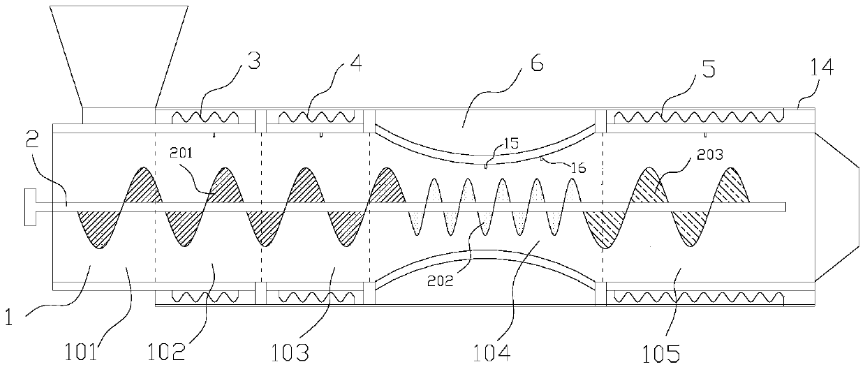
[0030] A kind of extrusion screw puffing cavity structure, please refer to figure 1 , including an expansion chamber 1 and a screw 2 housed in the cavity 1, wherein the expansion chamber 1 includes a feed conveying chamber 101 distributed sequentially from the feed end to the discharge end, the first section of high-temperature heating chamber 102, the second section The high-temperature heating chamber 103, the low-temperature heating chamber 104, the third high-temperature heating chamber 105, the first high-temperature heating chamber 102, the second high-temperature heating chamber 103, and the third high-temperature heating chamber 105 are respectively provided with first A high-temperature heating resistance wire 3, a second high-temperature heating resistance wire 4, and a third high-temperature heating resistance wire 5. A refrigerant chamber 6 is arranged outside the wall of the low-temperature heating chamber 104, and the wall of the low-temperature heating chamber 10...

Embodiment 2

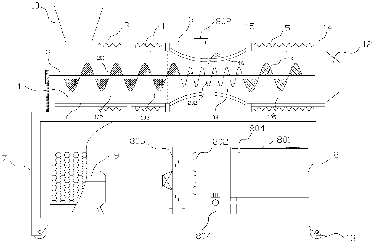
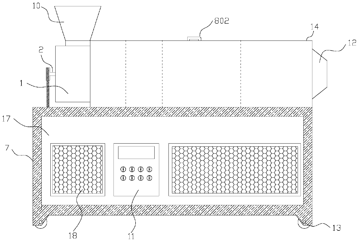
[0035] A kind of extruding screw expansion equipment, please refer to figure 2 , image 3 , Figure 4 , including an expansion chamber 1, a screw 2 accommodated in the expansion chamber 1, a frame 7, a molding channel 12 arranged at the discharge end of the expansion chamber 1, a motor 9 for driving the screw 2 to rotate, and an inlet arranged at the input end of the expansion chamber 1 Hopper 10, control cabinet 11, cooling system 8;

[0036] Among them, the cooling system 8 includes a refrigerant circulation box 801, a refrigerant inlet pipe 802 that communicates with the bottom of the refrigerant circulation box 801 at one end and communicates with the top of the refrigerant chamber 6 at one end. The refrigerant outlet pipe 803 connected to the bottom of the chamber 6, and the refrigerant circulation pump 804 arranged on the refrigerant inlet pipe 802;

[0037] The puffing chamber 1 includes a feed conveying chamber 101, a first-stage high-temperature heating chamber 10...

Embodiment 3

[0045] A processing method for starch-rich puffed food, using the extrusion screw puffing equipment in Example 2, feeding materials from the feed port 10, respectively controlling the first high-temperature heating chamber 102 and the second high-temperature heating chamber 103. The temperature of the low-temperature heating chamber 104 and the third-stage high-temperature heating chamber 105 is 70-90°C, 90-120°C, 40-65°C, and 90-120°C; the pressure of the low-temperature heating chamber 104 is controlled to be 10-20MPa.


PUM


Abstract

The invention provides an extrusion-screw puffing cavity structure. The structure comprises a puffing cavity and a screw accommodating in the cavity and is characterized in that the puffing cavity comprises a feeding conveying cavity, a first-segment high-temperature heating cavity, a second-segment high-temperature heating cavity, a low-temperature heating cavity and a third-segment high-temperature heating cavity which are distributed from a feeding end to a discharging end in sequence; a first-segment high-temperature heating resistance wire, a second-segment high-temperature heating resistance wire and a third-segment high-temperature heating resistance wire are arranged outside the cavity walls of the first-segment high-temperature heating cavity, the second-segment high-temperature heating cavity and the third-segment high-temperature heating cavity respectively, a refrigerant cavity is formed outside the cavity wall of the low-temperature heating cavity, and cavity wall of the low-temperature heating cavity is sunken inwards to be provided with a material passage the diameter of which is gradually decreased at first and then gradually increased. The cavity structure comprises the four segments of heating cavities including the first-segment high-temperature heating cavity, the second-segment high-temperature heating cavity, the low-temperature heating cavity and the third-segment high-temperature heating cavity, in this way, materials discharged from the cavity structure are subjected to heating processes of temperature increasing, temperature decreasing, temperatureincreasing and temperature decreasing, secondary temperature increasing and secondary temperature decreasing of the materials can be achieved, and puffed products with better quality are convenientlyobtained.

Description

technical field [0001] The invention belongs to the technical field of extrusion and puffing equipment, and in particular relates to an extrusion screw puffing cavity structure. Background technique [0002] Extrusion and puffing technology is a technology that integrates mixing, stirring, crushing, heating, cooking, sterilization, puffing and molding, and has a wide range of applications in the field of grain processing. The processing process of extrusion technology can generally be divided into three stages. The first stage is the material conveying stage. After entering the puffing chamber, the material is transported forward under the friction of the continuously rotating screw; And the pressure rises and the extrusion and shearing of the screw and the puffing chamber on the material, the material gradually melts; the third stage is the discharge stage, the temperature rises further, the starch, fat and protein change and react, and the material Discharges evenly throu...

Claims


Application Information

Patent Timeline
Patent Type & Authority Applications(China)
IPC IPC(8): A23L7/161
CPCA23L7/161
Inventor 林亲录赵思明李江涛韩文芳丁玉琴
Owner CENTRAL SOUTH UNIVERSITY OF FORESTRY AND TECHNOLOGY
Learn More