Closed core box with ejection mechanism

An ejector mechanism, closed technology, applied in casting and molding equipment and other directions, can solve the problems of shortening the service life of the mold, increasing the manufacturing cost, reducing the production efficiency, etc., and achieving the effect of prolonging the service life, reducing the degree of damage and improving the production efficiency.

Inactive Publication Date: 2019-08-09
STATE RUN NO 616 FACTORY
View PDF8 Cites 0 Cited by
  • Summary
  • Abstract
  • Description
  • Claims
  • Application Information

AI Technical Summary

Problems solved by technology

See figure 1 ; 1 is the lower core box; 2 is the upper core box; 3 is the core box hanging shaft; the sand filling port of the core box is arranged on the upper plane of the core box and parallel to the parting surface of the core box. Together and locked, fill the mixed resin sand or water glass sand into the core box through the sand filling port, scrape the sand filling port after shaking, and take out the mold after the core is cured, because the resin sand and water glass sand are solidified After that, it has a higher strength. When the mold is released, the core box needs to be placed vertically, and the bottom plates of the upper and lower core boxes are hit separately to generate vibration, so that there is a gap between the core and the core box, and then the hanging shaft on one side of the core box is hit to make it Separate from the other half of the core box. When the core box on one side is completely separated, hit the hanging shaft of the core box on the other side to separate the core from the core box. Because the striking force is transmitted to the core through the bottom of the core box and the hanging shaft , It takes a long time to hit the mold. This method not only reduces the production efficiency, but also easily causes damage to the core box and the core.
In the production process, problems such as core box deformation, cracking, and suspension shaft breakage often occur due to improper blows, which not only increases the maintenance cost of the mold, but also shortens the service life of the mold and increases the manufacturing cost.

Method used


Image

  • Closed core box with ejection mechanism
  • Closed core box with ejection mechanism

Examples


Embodiment Construction

[0021] In order to make the purpose, content and advantages of the present invention clearer, the specific implementation manners of the present invention will be further described in detail below in conjunction with the accompanying drawings and embodiments.

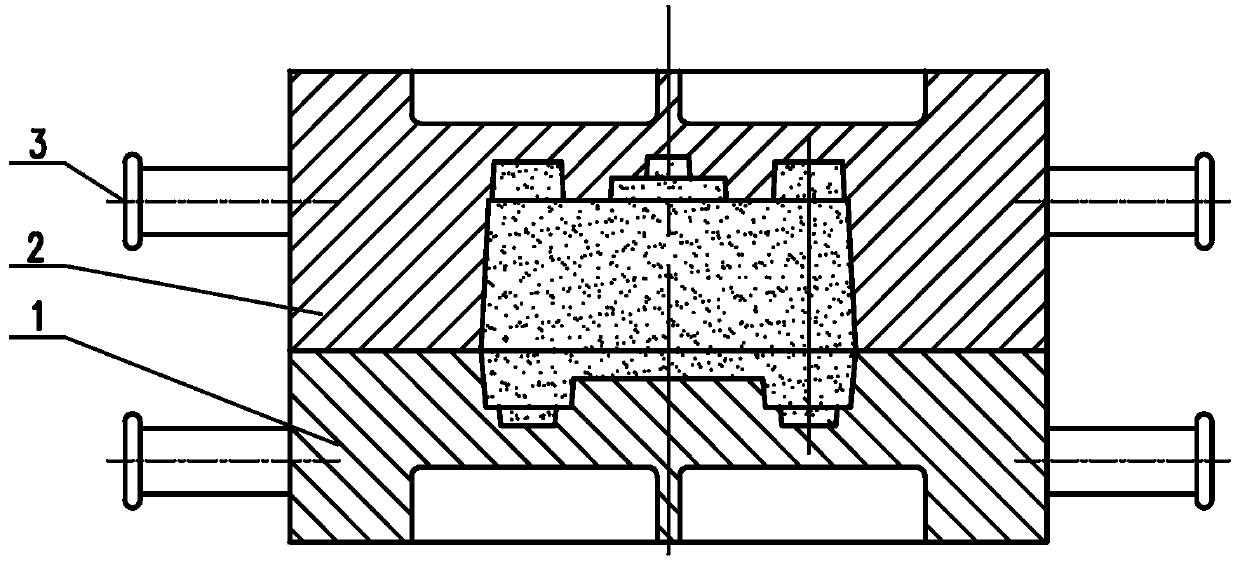
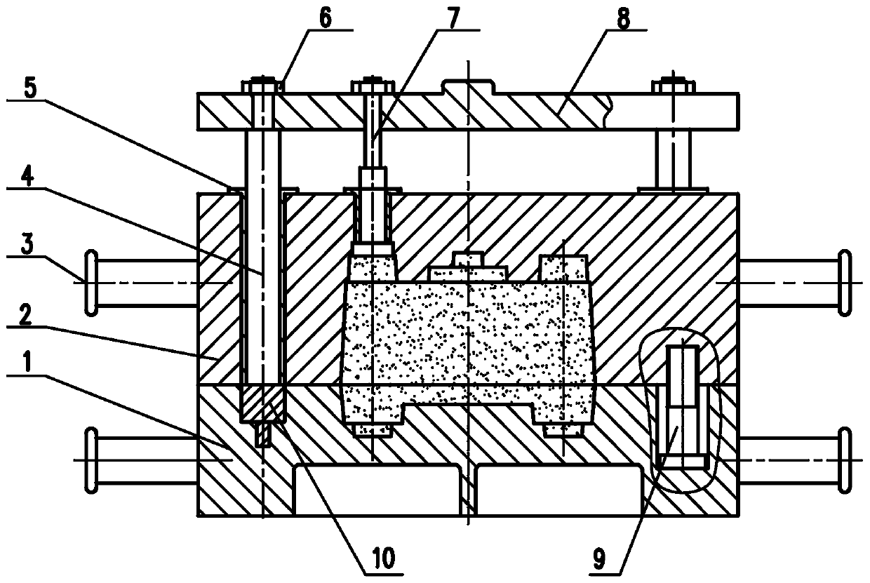
[0022] refer to figure 2 As shown, the closed core box with ejection mechanism of the present invention comprises: a lower core box 1, an upper core box 2 and a core box suspension shaft 3 arranged on the upper and lower core boxes; two core boxes are installed on the upper core box The box ejector rod 4 and a plurality of core ejector rods 7, the tops of the core box ejector rod 4 and the core ejector rod 7 protrude from the upper core box 2 and are fixed on the top which is arranged in parallel above the upper surface of the upper core box 2. On the ejection plate 8, the core box ejector rod 4 is located above the parting surface of the lower core box 1, and the core ejector rod 7 is located above the core.

[0023]...


PUM


Abstract

The invention belongs to the technical field of casting, and discloses a closed core box with an ejection mechanism. The closed core box comprises a lower core box body, an upper core box body and core box hoisting shafts arranged on the upper core box body and the lower core box body. The upper core box body is provided with two core box ejector rods and a plurality of core ejector rods, whereinthe top ends of the core box ejector rods and the core ejector rods protrude out of the upper core box body and are fixed to an ejector plate arranged above the top face of the upper core box body inparallel, the core box ejector rods are located above the parting surface of the lower core box body, and the core ejector rods are located above a core. The closed core box breaks through a method that a core box bottom plate and a hoisting haft are beaten for forming, wherein the method is constantly adopted; and through the forming method, the quality of the core is guaranteed, the production efficiency is improved, the core box damage degree is greatly reduced, and the service life of the core box is effectively prolonged.

Description

technical field [0001] The invention belongs to the technical field of casting, and relates to a closed core box with an ejection mechanism, in particular to the mold-out design of the closed core box made of resin sand and water glass sand. Background technique [0002] There are many structures of hand-made closed core boxes. There are two most commonly used ones, one is the horizontal split structure, and the other is the vertical split structure. The horizontal split core box is composed of upper and lower half core boxes. , both halves of the core box have shapes, and the sand filling port and sand scraping surface of the horizontal parting core box are parallel to the parting surface of the core box. The vertical parting core box is composed of left and right half core boxes, and the two half core boxes have shapes. The sand filling port and sand scraping surface of the vertical parting core box are perpendicular to the parting surface of the core box. The main differ...

Claims


Application Information

Patent Timeline
IPC IPC(8): B22C7/06
CPCB22C7/06B22C7/067
Inventor 侯建兵张世武刘继林师文琴孟祥松郭巨寿张耀
Owner STATE RUN NO 616 FACTORY
Why Eureka
Try Eureka