Encapsulation shell of wireless charging components, charging system, and charging device

A technology for wireless charging and encapsulation, which is applied to circuit devices, charging stations, vehicle components, etc., can solve the problems of difficult construction of wireless charging devices and damage to wireless charging devices, and achieves the effect of simple structure, cost saving, and convenient installation.

Active Publication Date: 2020-11-10
ZHENGZHOU YUTONG BUS CO LTD
View PDF6 Cites 0 Cited by
  • Summary
  • Abstract
  • Description
  • Claims
  • Application Information

AI Technical Summary

Problems solved by technology

[0003] The purpose of the present invention is to provide a wireless charging component packaging shell to solve the problems that the current wireless charging device is difficult to construct during the installation process and the wireless charging device is easily damaged by the natural environment

Method used


Image

  • Encapsulation shell of wireless charging components, charging system, and charging device
  • Encapsulation shell of wireless charging components, charging system, and charging device
  • Encapsulation shell of wireless charging components, charging system, and charging device

Examples


specific Embodiment 2

[0056] The specific embodiment 2 of the dynamic wireless charging system of the present invention, the difference between this embodiment and the above embodiment is only that: the overhead structure is replaced by Figure 5 In the overhead structure shown, the two ends of the overhead support plate are provided with support vertical plates to match bridging grooves of different depths.

specific Embodiment 3

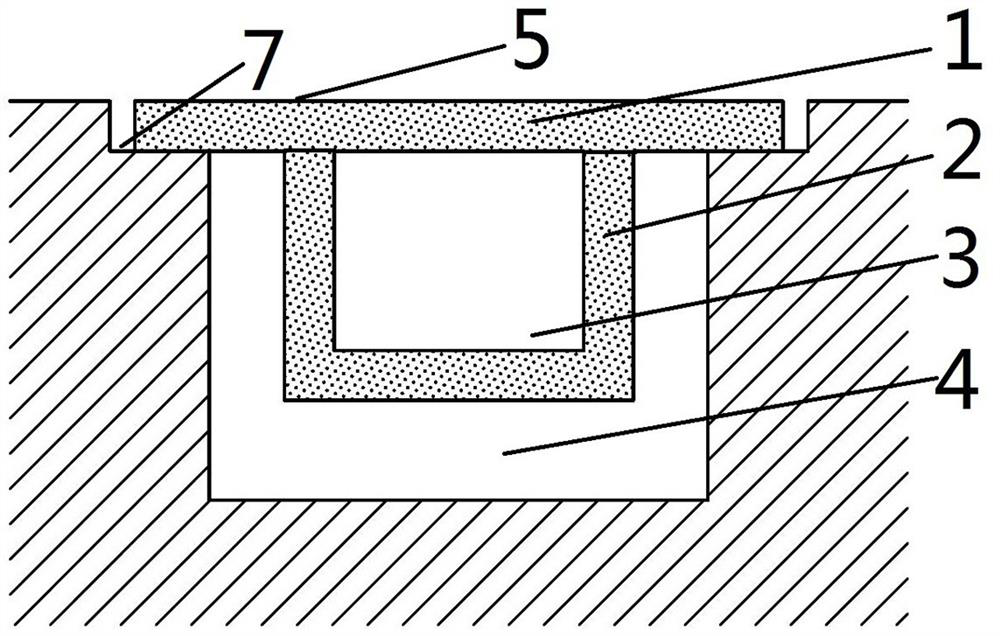
[0057] Specific embodiment 3 of the dynamic wireless charging system of the present invention, the difference between this embodiment and the above-mentioned embodiment is only that the overhead structure is replaced by Figure 6 As shown in the overhead structure, in this design, the housing itself contains a top cover, and the top cover of the housing itself is riveted or welded to the overhead support plate to achieve the effect of encapsulating the housing of the overhead wireless charging component.

specific Embodiment 4

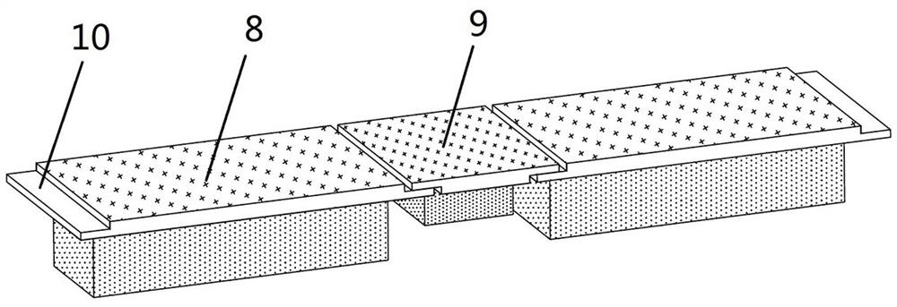
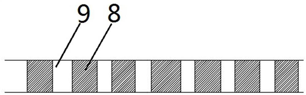
[0058] The specific embodiment 4 of the dynamic wireless charging system of the present invention, the difference between this embodiment and the above-mentioned embodiment is only that the laying method of the main section 8 and the auxiliary section 9 is replaced by the following Figure 7 In the arrangement shown, the two main sections 8 are overlapped with each other and then the auxiliary section 9 is overlapped.

[0059] The specific embodiment of the wireless charging component packaging shell of the present invention, the specific structure of the wireless charging component packaging shell is the same as the specific structure of the wireless charging component packaging shell described in any one of the above-mentioned specific embodiments 1-4 of the dynamic wireless charging system ,No longer.

[0060] The specific embodiment of the wireless charging device of the present invention, the specific structure of the wireless charging device is the same as the specific s...


PUM


Abstract

The invention relates to a wireless charging component packaging shell, a charging system, and a charging device, wherein the wireless charging component packaging shell includes a casing, and the casing has a chamber for accommodating the wireless charging component, and the casing is provided with an overhead housing for use. An overhead structure in which the encapsulation shell of the wireless charging component is suspended in the groove. With this overhead structure, the housing with the wireless charging component is overhead in the groove for loading the wireless charging device, avoiding direct contact with the ground while ensuring the connection between the wireless charging component and the receiving coil on the car or the horizontal plane The vertical distance solves the problem that the current wireless charging device is difficult to construct during the installation process, and the wireless charging device is easily damaged by the influence of the natural environment, and it also greatly saves the cost.

Description

technical field [0001] The invention relates to a wireless charging component packaging shell, a charging system, and a charging device. Background technique [0002] With the development of science and technology, the wide application of electric vehicles makes the charging of electric vehicles extremely important. At present, there are two charging methods for electric vehicles: 1. Wiring charging, 2. Wireless charging. Wiring charging is extremely inconvenient and has potential safety hazards; while wireless charging technology has many advantages such as no plugging and unplugging, high protection level, convenient and quick use, etc. At present, most of the wireless charging of electric vehicles uses wireless charging devices, and wireless charging devices include wireless charging components. and the wireless charging component packaging shell; the wireless charging component generally includes a wireless charging transmitting coil and a wireless charging accessory, an...

Claims


Application Information

Patent Timeline
Patent Type & Authority Patents(China)
IPC IPC(8): B60L53/12H02J50/10
CPCH02J50/10B60L53/38Y02T10/70Y02T90/14Y02T10/7072
Inventor 张瑞丰范志航刘威仝利锋宁小磊肖兴兴张龙飞胡大满
Owner ZHENGZHOU YUTONG BUS CO LTD
Why Eureka
Try Eureka