
Water-gas separating system

A water-gas separation and airflow technology, which is applied in separation methods, dispersed particle separation, gas treatment, etc., can solve the problems of the impact of gas transport efficiency, high construction cost and maintenance cost, and achieve the effect of low equipment cost and easy maintenance.

Active Publication Date: 2019-08-09
CHINA AIRPLANT STRENGTH RES INST
View PDF7 Cites 1 Cited by
  • Summary
  • Abstract
  • Description
  • Claims
  • Application Information

AI Technical Summary

Problems solved by technology

[0004] However, the above-mentioned water-gas separation schemes will affect the efficiency of gas transportation, and the cost and maintenance cost are high

Method used


Image

  • Water-gas separating system
  • Water-gas separating system

Examples


Embodiment Construction

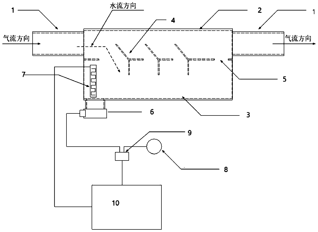
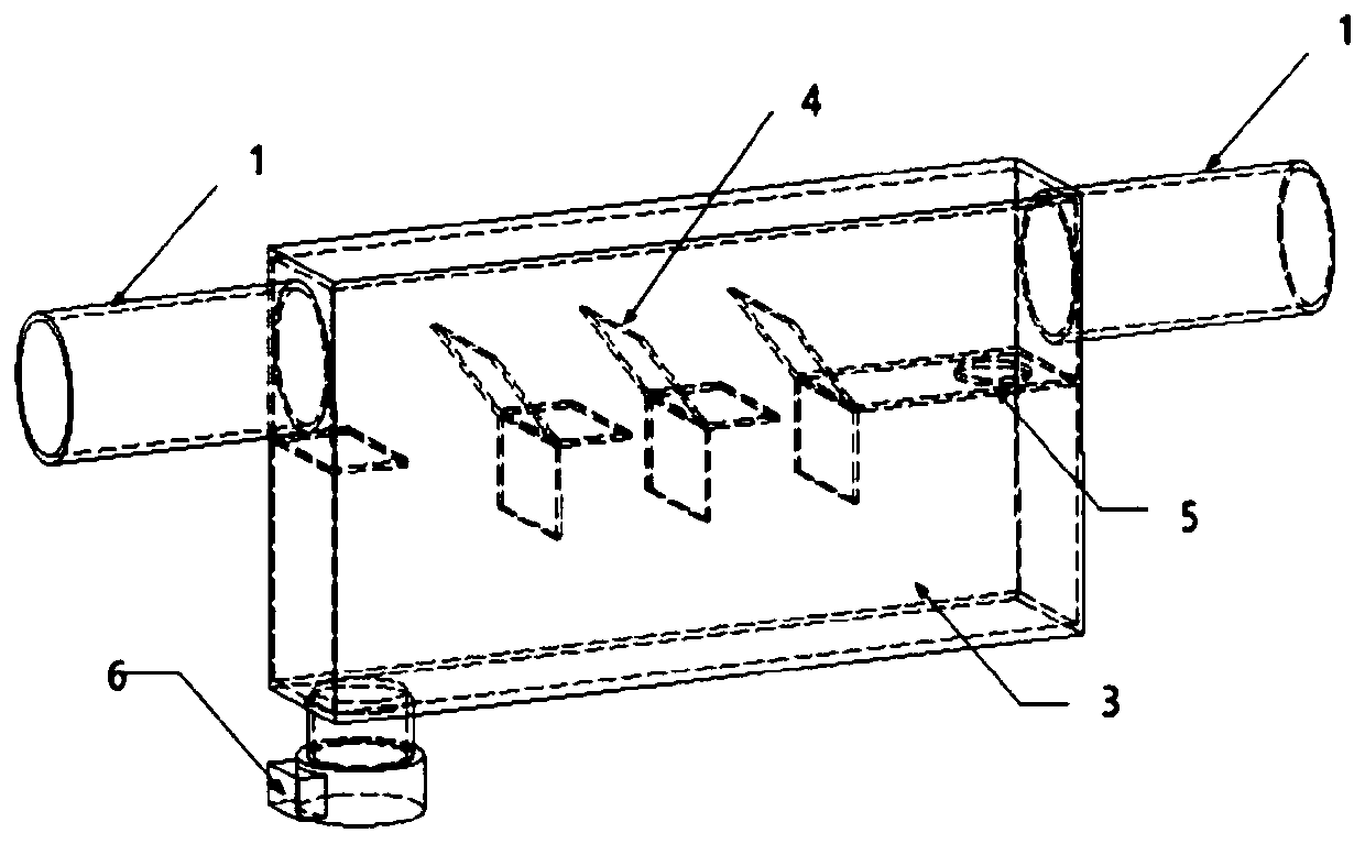
[0018] A specific embodiment of the present invention is: the water-gas separation system includes two parts, a mechanical structure and an electric control system. The mechanical part of the water-gas separation system is mainly the box of the water-gas separator. The water-gas separator box includes pipeline parts 2, water storage tank 3, water baffle 4, air guide hole 5 and other structures; the electric control system of the water-gas separation system includes a water level sensor 7, a single-chip microcomputer 10, a relay 9, and a power supply of the drainage pump 8. Drainage pump6.

[0019] Such as figure 1 As shown, the principle of the water-gas separation system is mainly that when the air flow (entrained water flow) flows through the water-gas separator through the pipeline, due to the high specificity of water, it flows through the lower part of the pipeline and passes through the baffle plate 4 to block the flow into the storage tank. The water tank 3, while the...


PUM


Abstract

The invention provides a water-gas separating system. The water-gas separating system comprises a box body; the upper half part of the box body is straight-going pipeline; the lower half part of the box body is a water storage groove; an original pipeline is connected with the two ends of the straight-going pipeline of the box body; a plurality of water stop plates are arranged in the box body inthe direction of the original pipeline; the water stop plates are arranged between the straight-going pipeline and the water storage groove; the left and right sides of the water stop plates are connected with the box body; a water drainage pump is arranged under the water storage groove; when the gas passes through the water-gas separating system, heavier water vapor can fall to positions under the water stop plates to be collected by the water storage groove; lighter dry gas is directly transmitted through an executing pipeline so as to achieve a water and gas separating effect; water and gas automatic separating, water storage and water drainage are realized on the basis of not affecting the airflow transmission efficiency; and moreover, the equipment cost is low, and the maintenance isconvenient.

Description

technical field [0001] The invention belongs to a water-gas separation system, in particular to a water-gas separation system used in aircraft inflation test equipment. Background technique [0002] In the aircraft inflation test, precise electronically controlled valves are generally used to control the air pressure changes, and the electronically controlled valves and their control circuits require that the air source must be dry and anhydrous, otherwise it will lead to unstable control or even damage the controller; in addition, the inflation test is a The air source gas is directly filled into the aircraft body, which also requires that the air source must be dry without excessive moisture. However, in actual equipment, due to reasons such as gas compression and condensation or rainwater infiltration, there is often a large amount of water in the gas source that is difficult to discharge. [0003] Using existing dryers and other equipment on the market to separate the m...

Claims


Application Information

Patent Timeline
Patent Type & Authority Applications(China)
IPC IPC(8): B64F5/60B01D53/26
CPCB64F5/60B01D53/26B01D2257/80
Inventor 高建
Owner CHINA AIRPLANT STRENGTH RES INST
Learn More