Bottom lifting plate steel wire transmission mechanism of telescopic structure

A technology of telescopic structure and bottom plate, which is applied in the field of textile manufacturing, and can solve problems such as the friction and slippage between the wire feeding wheel and the blocking wire, the blocking wire cannot be drawn out, and the blocking wire is bent and deformed.

Pending Publication Date: 2019-08-09
ZHONGSHAN LONGZU AUTOMATION TECH CO LTD
View PDF1 Cites 4 Cited by
  • Summary
  • Abstract
  • Description
  • Claims
  • Application Information

AI Technical Summary

Problems solved by technology

[0007] The purpose of the present invention is to provide a telescopic structure lifter steel wire transmission mechanism to solve the above-mentioned background technology because the wire feeding wheel is a circular structure, which is easy to cause the blockage wire to bend and deform, resulting in the blockage wire not being able to pass through smoothly when threading. In, the friction between the yarn and the blocking wire is relatively large, which makes it difficult to draw the wire, and the friction between the feeding wheel and the blocking wire increases and slips, and the problem that the blocking wire cannot be pulled out and the blocking wire is often broken

Method used


Image

  • Bottom lifting plate steel wire transmission mechanism of telescopic structure
  • Bottom lifting plate steel wire transmission mechanism of telescopic structure
  • Bottom lifting plate steel wire transmission mechanism of telescopic structure

Examples


Embodiment 1

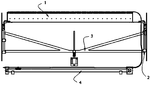
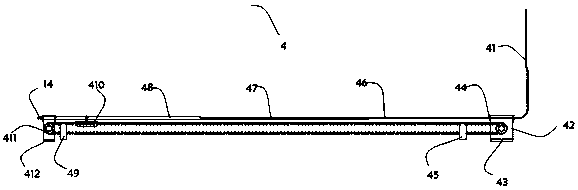
[0032] The invention provides a telescopic structure lifter steel wire transmission mechanism, such as figure 1 and figure 2 As shown, it includes a bottom lifting needle plate 1, a first lifting device 2, a second lifting device 3 and a wire drawing device 4. The wire feeding device 4 includes a synchronous belt 44, and one end of the synchronous belt 44 is equipped with a feeder for driving the synchronous belt 44 to rotate. Wire motor 42, the other end transmission of synchronous belt 44 is connected with belt fixed pulley 411, and belt connection block 410 is installed on the synchronous belt 44, and the top of belt connection block 410 is equipped with third-stage telescopic sleeve 48, and the third-stage telescopic sleeve A second-stage telescopic sleeve 47 is sleeved inside the pipe 48, and a first-stage telescopic sleeve 46 is sleeved inside the second-stage telescopic sleeve 47. A steel wire conduit 41 is installed on one end of the first-stage telescopic sleeve 46, ...

Embodiment 2

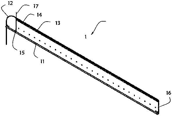
[0039] As the second embodiment of the present invention, in order to facilitate hanging cloth work, the inventors improved the bottom lifting needle plate 1, as a preferred embodiment, as image 3 As shown, the starting needle plate 1 includes a base plate 11, one end of the base plate 11 is provided with a small steel wire conduit 12, and the top of the base plate 11 is provided with a plurality of primer needles 13, and the steel wire 14 passes through the small steel wire conduit 12 And be connected on the primer needle 13.

[0040] In this embodiment, the steel wire conduit 12 communicates with the steel wire conduit 41 , so that the steel wire 14 passes through the steel wire conduit 41 and enters the steel wire conduit 12 .

[0041] One end of the lifting motherboard 11 is equipped with a steel wire reset fixing pipe 15, and the other end of the lifting motherboard 11 is equipped with a steel wire in place signal line 16, and the top of the steel wire reset fixing pipe ...

Embodiment 3

[0044] As a third embodiment of the present invention, in order to drive the lifting work of the bottom lifting needle plate 1, the inventors are also provided with a first lifting device 2 and a second lifting device 3, as a preferred embodiment, as Figure 4 and Figure 5 As shown, the first lifting device 2 includes a lifting device fixing plate 21, a linear bearing 24 is installed on the outer wall of the lifting device fixing plate 21, a connecting seat 23 is installed on the linear bearing 24, and one end of the connecting seat 23 is provided with a threading plate connecting rod 22 , the outer wall of the lifting device fixing plate 21 is also provided with the highest position sensor 25, the bottom of the highest position sensor 25 is equipped with a linear guide rail 26, the bottom of the linear guide rail 26 is provided with a reset sensor 27, and the second lifting device 3 includes a connecting frame 32, the bottom of the connecting frame 32 is equipped with a lift...


PUM


Abstract

The invention relates to the technical field of textile manufacturing, in particular to a bottom lifting plate steel wire transmission mechanism of a telescopic structure. The mechanism comprises a bottom lifting needle plate, a first lifting device, a second lifting device and a steel wire drawing device. In the bottom lifting plate steel wire transmission mechanism of the telescopic structure, asteel wire is arranged in a first-stage telescopic sleeve, a second-stage telescopic sleeve and a third-stage telescopic sleeve, so that it is guaranteed that the steel wire cannot be bent or deformed by protecting the steel wire through the first-stage telescopic sleeve, the second-stage telescopic sleeve and the third-stage telescopic sleeve in a normal state, and the problem that smooth penetrating cannot achieved when the locking wire penetrates. The first-stage telescopic sleeve, the second-stage telescopic sleeve and the third-stage telescopic sleeve which are guided by the steel wire are each of the telescopic structure and adopt a telescopic sleeve structure, the friction resistance of the steel wire is reduced, and the problems that the locking wire cannot be pulled out and the locking wire is broken are avoided.

Description

technical field [0001] The invention relates to the technical field of textile manufacturing, in particular to a steel wire transmission mechanism for a bottom plate with a telescopic structure. Background technique [0002] At present, the wire feeding mechanism of the lifting plate device of the computerized flat knitting machine, such as the authorized announcement number CN207958632U, is a wire feeding mechanism for the lifting plate. Respectively make the second driving member of reverse rotation, and the blocking wire is clamped between the wheel surfaces of the two wire feeding wheels. When the two wire-feeding wheels rotate in opposite directions respectively, the wire-feeding is realized through the rolling friction force of the two wire-feeding wheel surfaces on the blocking wire respectively, and the blocking wire is penetrated or pulled out from the pinhole of the bottom comb. [0003] However, the following technical problems are often exposed in the actual use...

Claims


Application Information

Patent Timeline
Patent Type & Authority Applications(China)
IPC IPC(8): D04B15/00D04B15/90
CPCD04B15/00D04B15/90
Inventor 陈雪梅
Owner ZHONGSHAN LONGZU AUTOMATION TECH CO LTD
Why Eureka
Try Eureka