
A long-span composite structure floor

A combined structure and large-span technology, which is applied to floors, building components, building structures, etc., can solve the problems of limited structural strength of prefabricated floor slabs, high density of concrete columns, and large number of concrete columns, and achieve excellent seismic performance, The effect of improving structural strength and improving toughness

Active Publication Date: 2020-10-16
XIANGTAN UNIV
View PDF7 Cites 0 Cited by
  • Summary
  • Abstract
  • Description
  • Claims
  • Application Information

AI Technical Summary

Problems solved by technology

[0004] However, due to the limited structural strength of prefabricated floor slabs and the large number of concrete columns per unit area of ​​prefabricated floor slabs, the density of concrete columns in the building floors is high, which greatly restricts the architectural design in the building floors.

Method used


Image

  • A long-span composite structure floor
  • A long-span composite structure floor
  • A long-span composite structure floor

Examples


Embodiment 1

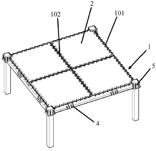
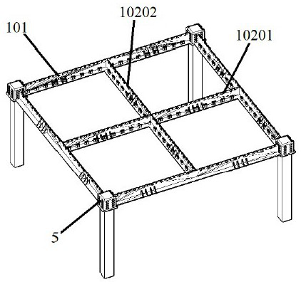
[0090] A long-span composite structure floor includes: a composite steel beam structure 1 and a prefabricated floor slab 2 . The composite steel beam structure 1 includes: an outer frame steel beam 101 and an inner cross steel beam 102 . The outer frame steel beam 101 is connected with the concrete column. The inner cross steel beam 102 is erected on the outer frame steel beam 101 and located inside the rectangular frame formed by the outer frame steel beam 101 . The outer frame steel beam 101 and the inner cross steel beam 102 form a "Tian"-shaped structure. The prefabricated floor slab 2 is arranged in the box formed by the outer frame steel beam 101 and the inner cross steel beam 102 .

Embodiment 2

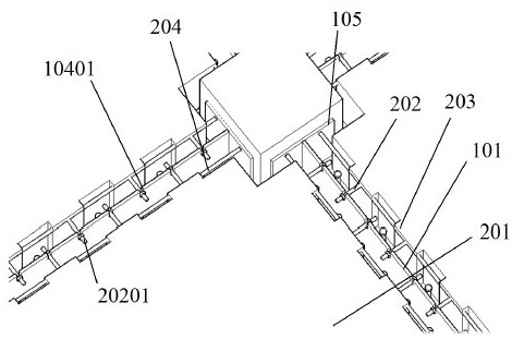
[0092] Embodiment 1 is repeated, except that the large-span composite structure floor further includes: a guiding and clamping mechanism 3 . The guiding and clamping mechanism 3 includes: a supporting arm 301 , a clamping arm 302 , and a rotating shaft 303 . The supporting arm 301 is fixedly connected with the clamping arm 302 . The rotating shaft 303 is disposed at the joint of the supporting arm 301 and the clamping arm 302 . The rotating shaft 303 is installed on the contact surface between the prefabricated floor slab 2 and the composite steel beam structure 1 . The supporting arm 301 is located at the bottom of the prefabricated floor slab 2 . The clamping arm 302 is in contact with the edge side of the prefabricated floor slab 2 .

Embodiment 3

[0094] Embodiment 1 is repeated, except that the large-span composite structure floor further includes: an installation guide structure 4 . The installation guide structure 4 is a guide rib. The installation guide structure 4 is arranged on the contact surface between the prefabricated floor slab 2 and the composite steel beam structure 1 . The installation guide structure 4 is provided with a guide slope 401 . The bottom of the guide slope 401 is in contact with the prefabricated floor slab 2 . The guiding slope 401 is a plane, or the guiding slope 401 is a curved surface.


PUM


Abstract

The invention discloses a large-span composite structure floor. The large-span composite structure floor comprises a combined steel beam structure and a prefabricated floor plate. The combined steel beam structure includes an outer frame steel beam and an inner cross-shaped steel beam. The outer frame steel beam is connected with a concrete column. The inner cross-shaped steel beam is erected on the outer frame steel beam and is located in a rectangular frame formed by the outer frame steel beam. The outer frame steel beam and the inner cross-shaped steel beam form a structure in the shape like a Chinese character ''tian''. The prefabricated floor plate is disposed in a square frame formed by the outer frame steel beam and the inner cross-shaped steel beam. The large-span composite structural floor enables the overall outer frame steel beam structure to have a larger span, the density of concrete columns in a building is reduced, the design difficulty in building floors is reduced, andthe diversity of the building floor design is improved.

Description

technical field [0001] The invention relates to a floor, in particular to a large-span combined structure floor, which belongs to the technical field of construction engineering. Background technique [0002] The cast-in-place integral floor is widely used in ordinary reinforced concrete structures because of its good integrity and strong seismic performance. However, there are many wet operations on site, heavy weight, complicated procedures, long construction period, and a large amount of formwork on site; in addition, the bottom of the concrete slab is prone to cracking, the span of the floor slab is limited, and the column network is too dense. [0003] The prefabricated floor has the advantages of fast construction speed, clean construction site, saving building materials, and high degree of industrialization. More and more prefabricated floors are used in actual projects; the existing prefabricated floors mostly use reinforced truss floor decks , Profiled steel compos...

Claims


Application Information

Patent Timeline
Patent Type & Authority Patents(China)
IPC IPC(8): E04B5/02E04B5/10
CPCE04B5/02E04B5/10
Inventor 陈俊刘哲许福龙士国杨才千刘雨晴陈超王开吴蒙彭月陈绪林胥卉
Owner XIANGTAN UNIV
Learn More