
Engine and oscillator monitoring and controlling device for pavement forming machine

A monitoring control and engine technology, applied in engine control, machine/engine, engine components, etc., can solve the problems of increasing difficulty in construction organization, low overall paving work efficiency, and high price

Pending Publication Date: 2019-08-09
SHIJIAZHUANG CHENQI TECH
View PDF0 Cites 1 Cited by
  • Summary
  • Abstract
  • Description
  • Claims
  • Application Information

AI Technical Summary

Problems solved by technology

[0002] At present, with the rapid development of my country's economy, the construction of high-grade highways is becoming more and more intensive, and the cement concrete pavement is getting more and more attention from road construction units. There are currently two types of pavers for cement concrete pavement construction on the market. , one is the track-type cement concrete paver, the track-type cement concrete paver needs to erect the track formwork, the construction process is more complicated, requires more manpower, the construction organization is more difficult, and the overall work efficiency of the paving operation is not high. It is difficult to adapt to projects with short construction period and fast progress
Another type of paver that is widely used is the large concrete slip form paver. The slip form of this paver can directly form the side of the road without additional manual installation of formwork, and the degree of construction automation has been improved. However, The paver itself cannot automatically distribute materials, which affects the construction speed, and the price is relatively high. For general road builders or rural road builders, this equipment exceeds the purchasing power of the construction unit.

Method used


Image

  • Engine and oscillator monitoring and controlling device for pavement forming machine
  • Engine and oscillator monitoring and controlling device for pavement forming machine
  • Engine and oscillator monitoring and controlling device for pavement forming machine

Examples


Embodiment Construction

[0033] The technical solutions in the embodiments of the present invention are clearly and completely described below in conjunction with the accompanying drawings in the embodiments of the present invention. Obviously, the described embodiments are only part of the embodiments of the present invention, not all of them. Based on the embodiments of the present invention, all other embodiments obtained by persons of ordinary skill in the art without making creative efforts belong to the protection scope of the present invention.

[0034] In the following description, a lot of specific details are set forth in order to fully understand the present invention, but the present invention can also be implemented in other ways different from those described here, and those skilled in the art can do it without departing from the meaning of the present invention. By analogy, the present invention is therefore not limited to the specific examples disclosed below.

[0035] Such as figure ...


PUM


Abstract

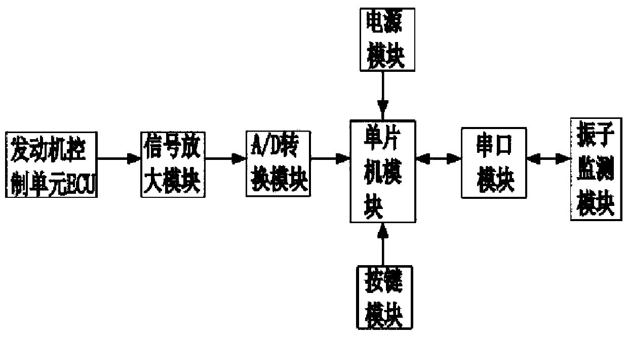
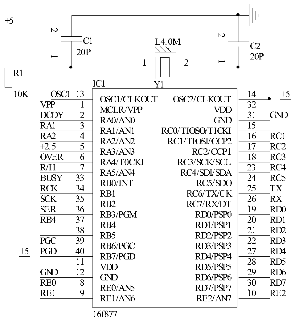
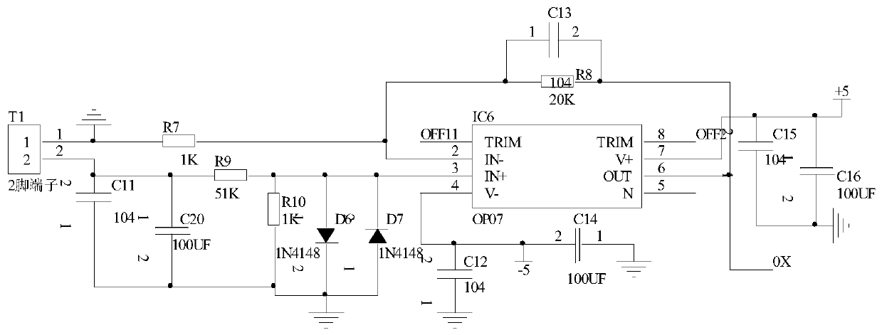
The invention discloses an engine and oscillator monitoring and controlling device for a pavement forming machine. The engine and oscillator monitoring and controlling device comprises a single chip microcomputer module. A serial port module is in both-way connection with the single chip microcomputer module, is in both-way connection with an oscillator monitoring module and is used for receivingrelevant oscillator information acquired by the oscillator monitoring module. Engine rotating speed signals output by an engine control unit (ECU) is input into the input end of a signal amplificationmodule. The output end of the signal amplification module is connected with the signal input end of an A / D conversion module. The signal output end of the A / D conversion module is connected with thesignal input end of the single chip microcomputer module. After amplification and A / D conversion of the engine rotating speed signals are completed, the engine rotating speed signals are delivered into the single chip microcomputer module for processing. A key module is connected with the single input end of the single chip microcomputer module and used for inputting a control command. By means ofthe device, monitoring over an engine and an oscillator of the pavement forming machine can be achieved; and the working states of the engine and the oscillator are controlled according to the monitoring result.

Description

technical field [0001] The invention relates to the technical field of road surface forming machine monitoring, in particular to a road surface forming machine engine and vibrator monitoring and control device. Background technique [0002] At present, with the rapid development of my country's economy, the construction of high-grade highways is becoming more and more intensive, and the cement concrete pavement is getting more and more attention from road construction units. There are currently two types of pavers for cement concrete pavement construction on the market. , one is the track-type cement concrete paver, the track-type cement concrete paver needs to erect the track formwork, the construction process is more complicated, requires more manpower, the construction organization is more difficult, and the overall work efficiency of the paving operation is not high. It is difficult to adapt to projects with short construction period and fast progress. Another type of pav...

Claims


Application Information

Patent Timeline
Patent Type & Authority Applications(China)
IPC IPC(8): F02D11/00F02B77/08E01C19/38G01P3/44
CPCF02D11/00F02B77/08E01C19/38G01P3/44
Inventor 张军张会杰
Owner SHIJIAZHUANG CHENQI TECH
Learn More