Pressure reducing valve with pressure chamber

A pressure chamber and pressure reducing valve technology, applied in the field of pressure reducing valves

Pending Publication Date: 2019-08-09
GENTECSHANGHAI
View PDF0 Cites 3 Cited by
  • Summary
  • Abstract
  • Description
  • Claims
  • Application Information

AI Technical Summary

Problems solved by technology

[0009] In view of the problems existing in the actual use of existing pressure reducing valves with pressure chambers, the purpose of the present invention is to provide a highly reliable solution for pressure reducing valves with pressure chambers

Method used


Image

  • Pressure reducing valve with pressure chamber
  • Pressure reducing valve with pressure chamber
  • Pressure reducing valve with pressure chamber

Examples


Embodiment Construction

[0024] In order to make the technical means, creative features, goals and effects achieved by the present invention easy to understand, the present invention will be further described below in conjunction with specific illustrations.

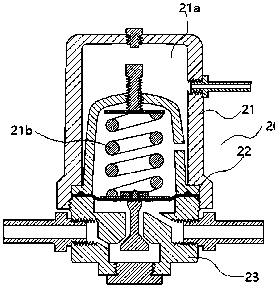
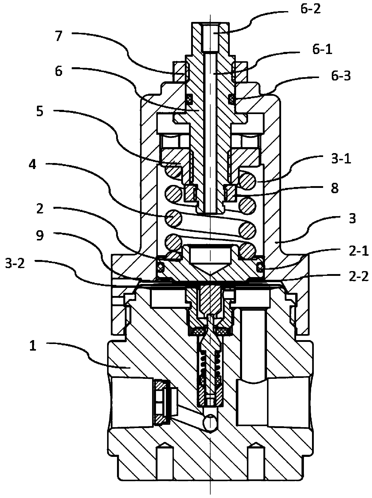
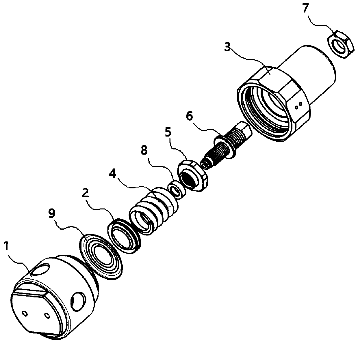
[0025] According to the structural characteristics of the diaphragm pressure reducing valve, a piston structure is added on the diaphragm in the pressure reducing valve, so that a pressure chamber is formed inside the pressure reducing valve, and the pressure of the pressure chamber is converted into a loading force through the piston. At the same time, the diaphragm is protected from the upper side, so that the diaphragm is only subjected to internal pressure and not external pressure, and the internal pressure acts on the piston structure to limit the protection. In this way, even if the diaphragm is broken, the working gas and the control gas are completely isolated, and the two gases do not interfere with each other. The piston acts as a spar...


PUM


Abstract

The invention discloses a pressure reducing valve with a pressure cavity. The pressure reducing valve with the pressure cavity can change the output pressure of the pressure reducing valve by externally pressurizing or relieving the pressure of the pressure cavity. The pressure reducing valve with the pressure cavity comprises an adjusting assembly with a pressure cavity, a membrane, a valve coreassembly and a piston assembly, wherein the piston assembly is hermetically arranged in the adjusting assembly;and one end of the piston assembly is matched with a pressure regulating spring in the adjusting assembly, and the other end of the piston assembly is matched with the membrane. According to the scheme, the advantages of a membrane pressure reducer are retained, the membrane pressure reducer also has a safety protection function under the rupture of a membrane, when the membrane breaks down, a valve core cannot be completely opened even under the action of the spring force, and gas can still be normally conveyed; and furthermore, the membrane is only limited and protected by the inner pressure and the outer pressure, and the inner pressure is limited and protected by the piston assembly, so that the probability of rupture of the membrane is relatively low during breaking down, and the problems in the prior art are effectively overcome.

Description

technical field [0001] The invention relates to the technology of a pressure reducing valve, in particular to the technology of a pressure reducing valve with a pressure cavity (DOME). Background technique [0002] It is often necessary to use different gases in many fields of industry, such as industrial gas welding, laboratory inspection, semiconductor industry or food packaging industry and other fields. For the convenience of storage and transportation, gas is usually compressed and stored in high-pressure gas cylinders. When in use, the gas pressure must be reduced to the required pressure through a pressure reducing valve as needed. [0003] In specific applications, there is a single bottle used, and the pressure reducing valve only needs a single pressure reducing function. In order to facilitate centralized control and management, there are also application methods that use high-pressure gas cylinders for centralized gas supply. In addition to the decompression fun...

Claims


Application Information

Patent Timeline
IPC IPC(8): F16K17/30F16K17/40F16K37/00F16J1/02
CPCF16K17/30F16K17/403F16K37/0025F16J1/02
Inventor 胡跃钢龚如意
Owner GENTECSHANGHAI
Why Eureka
Try Eureka