Train phase separation passing converter

A technology of over-phase splitting and converters, applied in the field of over-phase splitting, can solve problems such as difficulty in governance and cost of governance, asymmetric distribution of three phases, and impact on normal operation of trains, etc., to improve auxiliary heat dissipation performance, improve heat dissipation performance, and facilitate The effect of assembling extensions

Active Publication Date: 2019-08-09
ZHUZHOU CSR TIMES ELECTRIC CO LTD
View PDF6 Cites 2 Cited by
  • Summary
  • Abstract
  • Description
  • Claims
  • Application Information

AI Technical Summary

Problems solved by technology

During the operation, the train will pass through the phase-separation area frequently. During this process, if the train is not properly controlled, it will cause the train to be loaded into the phase-separation area, which will easily cause the train traction converter, traction transformer, pantograph and line catenary to burn. damage and other accidents, which seriously endanger the safety of the line and affect the normal operation of the train
The electrified railway traction power supply system has the characteristics of three-phase distribution asymmetry, impact, and nonlinearity for the external power system. Under the current grid conditions, when the train brakes, the braking energy doubled is directly fed back to the grid. It will lead to a more serious decline in the power quality of the power grid, which will become an important factor affecting the safe and stable operation of the power system and electric railway load, and the difficulty and cost of governance will also be greatly increased

Method used


Image

  • Train phase separation passing converter
  • Train phase separation passing converter
  • Train phase separation passing converter

Examples


Embodiment Construction

[0030] The present invention will be further described below in conjunction with the accompanying drawings and specific embodiments.

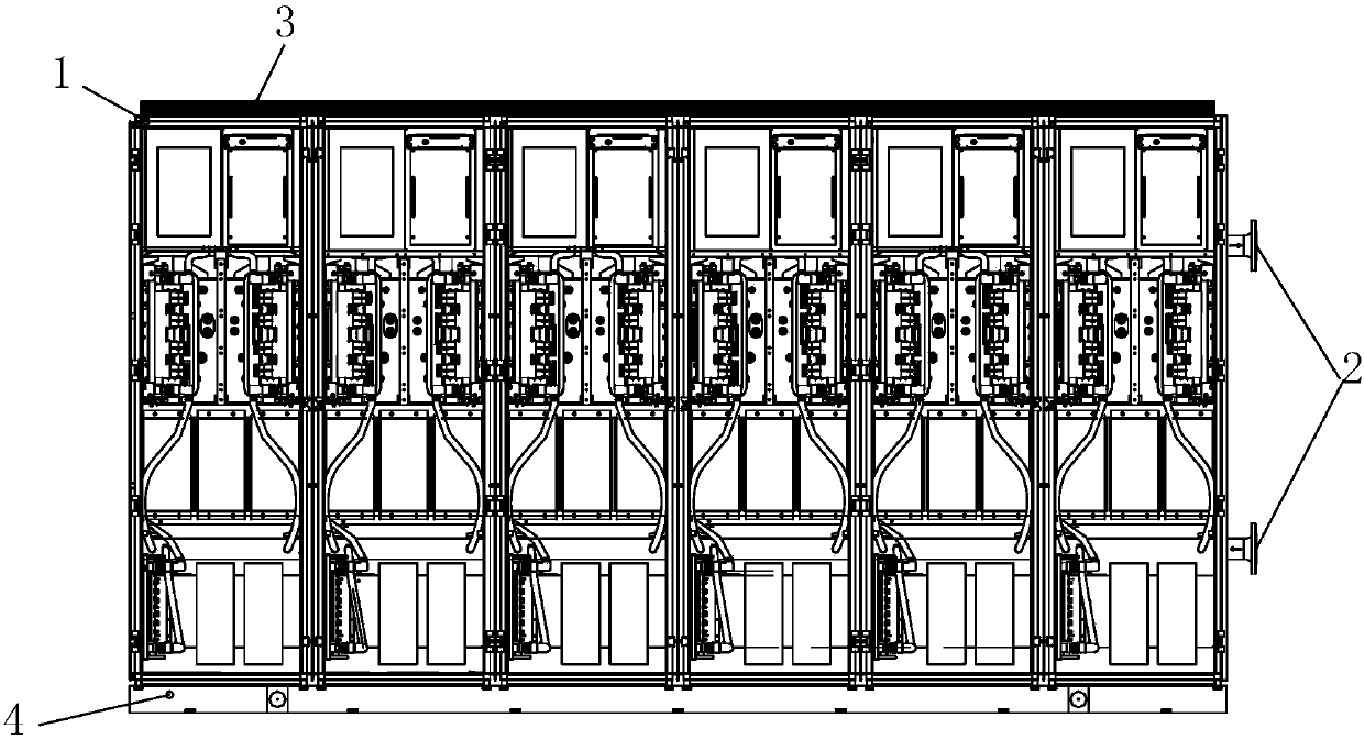
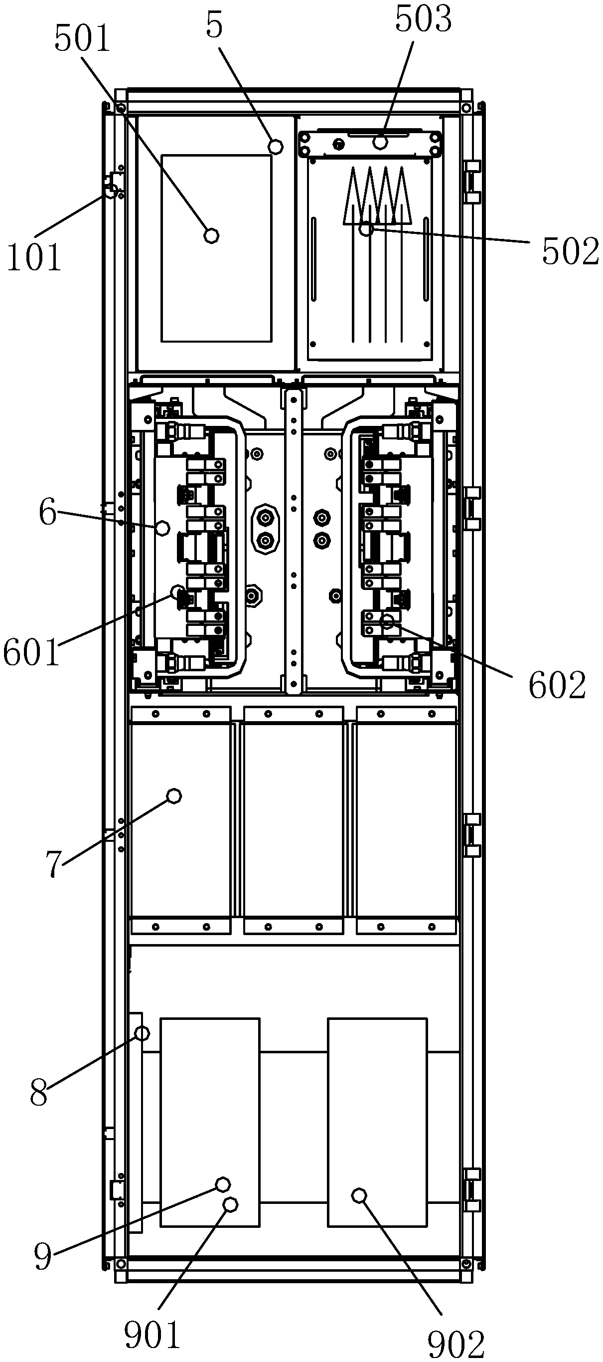
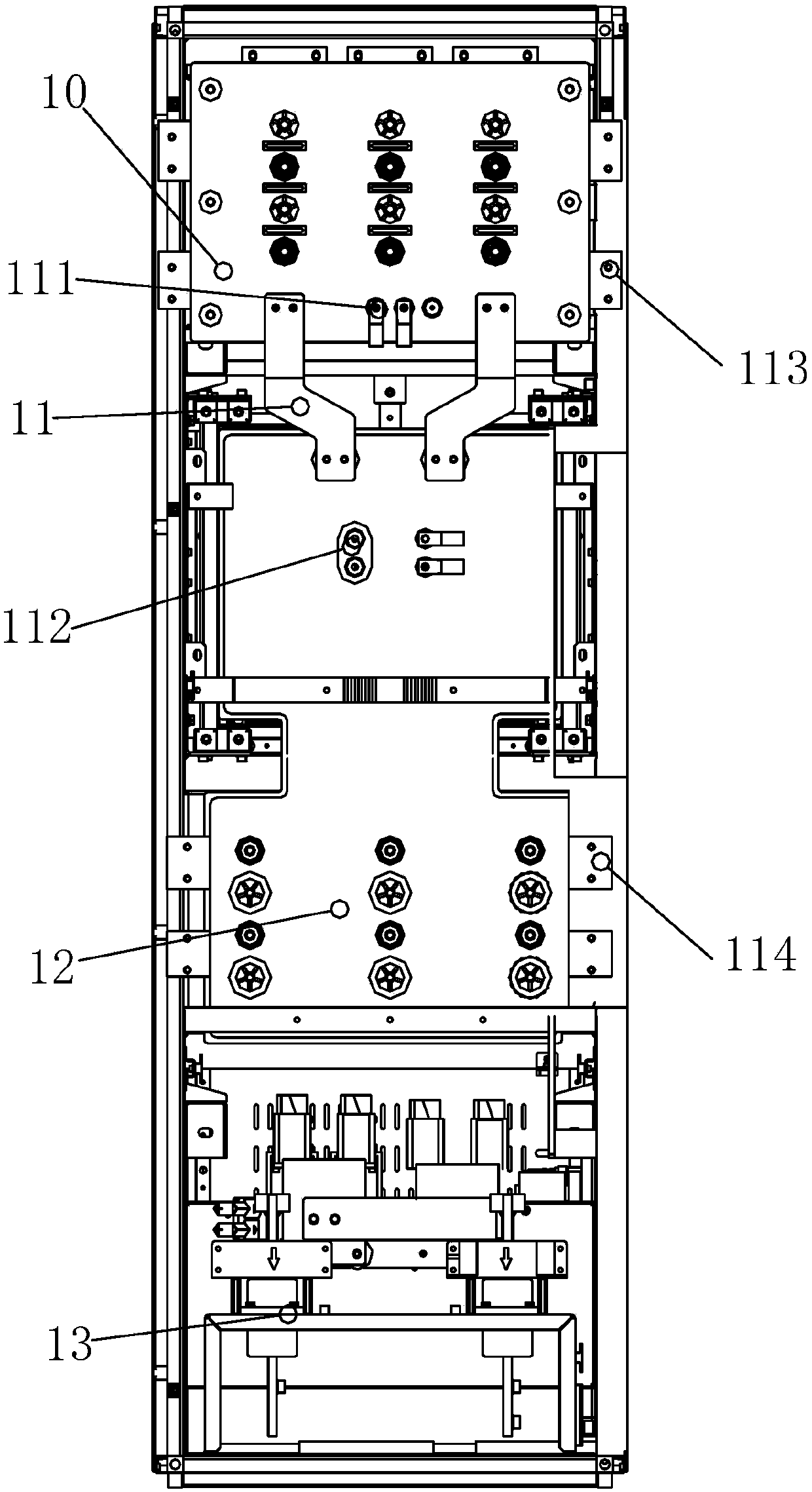
[0031] Such as Figure 1 to Figure 8 As shown, the train over-phase converter of this embodiment includes a base 4 and a plurality of unit cabinets 1, and a plurality of unit cabinets 1 are installed side by side on the base 4, and each unit cabinet 1 has the same structure; the unit cabinet 1 includes a cabinet body 101. Electric control component 5, power module component 6, support capacitor 7, discharge resistor component 8, contactor component 9, resonant capacitor 14 and wiring component 13; cabinet 101 is provided with multiple support beams 103, electric control component 5 , the power module assembly 6, the support capacitor 7 and the contactor assembly 9 are installed on the support beam 103 of the cabinet 101 from top to bottom, the resonant capacitor 14 is installed side by side with the electric control assembly 5 and is located on...


PUM


Abstract

The invention discloses a train phase separation passing converter comprising a base and multiple unit cabinets. Multiple unit cabinets are arranged on the base in parallel. Each unit cabinet comprises a cabinet body, an electric control component, a power module component, a support capacitor, a discharge resistance component, a contactor component, a resonance capacitor and a wiring component. Multiple support beams are arranged in the cabinet body. The electric control component, the power module component, the support capacitor and the electric control component are sequentially installedon the support beams of the cabinet body from top to bottom. The resonance capacitance and the electric control component are installed side by side and located on the rear side of the cabinet body. The discharge resistance component is installed on one side of the cabinet body in front of the contactor component. The wiring component is installed on the rear side of the contactor component. The train phase separation passing converter has the advantages of simple and compact structure, reasonable layout, good expansion performance, good heat dissipation performance and the like.

Description

technical field [0001] The invention mainly relates to the technical field of phase separation, in particular to a phase separation converter for trains. Background technique [0002] my country's electrified railway generally adopts single-phase power frequency AC system. In order to make the three-phase load of the power system as balanced as possible, the electrified railway often adopts the scheme of alternating phase sequence and phase-separated partition power supply. The adjacent power supply intervals at the phase-separation partition are divided by air or insulators to form insulating electrical phase separation, referred to as electrical phase separation or phase separation. This power supply method has the problem of excessive phase separation of train power failure, especially in heavy load and climbing sections, which reduces the running speed of the train and reduces the railway transportation capacity. During the operation, the train will pass through the pha...

Claims


Application Information

Patent Timeline
Patent Type & Authority Applications(China)
IPC IPC(8): H02M1/00H05K7/20
CPCH02M1/00H05K7/20918H05K7/20927
Inventor 俞鹏程孙保涛刘猛杨鸣远仇乐兵邱文俊曹强杨晓宇黄华坤肖宇翔
Owner ZHUZHOU CSR TIMES ELECTRIC CO LTD
Why Eureka
Try Eureka