
A quantum cascade laser structure with high-efficiency lateral heat conduction and its preparation method

A quantum cascade and laser technology, which is applied in the direction of semiconductor lasers, semiconductor laser devices, lasers, etc., can solve the problems of the waveguide’s ability to limit the injection current, increase the laser waveguide loss, and increase the threshold current density. Problems such as improving electro-optic conversion efficiency, reduced injection current leakage, and reduced heat generation

Active Publication Date: 2017-10-03
吉光半导体科技有限公司
View PDF3 Cites 0 Cited by
  • Summary
  • Abstract
  • Description
  • Claims
  • Application Information

AI Technical Summary

Problems solved by technology

[0003] Due to the high heat generation in the active region of quantum cascade lasers, even though the commonly used wet-etched double-channel ridge waveguide is better than the dry-etched double-channel ridge waveguide in terms of device heat dissipation, it causes waveguide damage. The limiting ability of the injection current is reduced; in addition, the wet-etched double-channel ridge waveguide quantum cascade laser, the TM mode laser of its lasing is coupled to the surface plasmon at the interface between the electrical insulating layer and the electrode metal, which increases the laser The waveguide loss increases the threshold current density, but this phenomenon does not occur in dry-etched double-channel ridge waveguide devices (reference: Xue Huang, et al, OpticsExpress, Vol.20, Issue 3, pp.2539-2547( 2012))
Therefore, in practical applications, in order to ensure the high performance and stable operation of quantum cascade lasers in various fields, it is necessary to control the temperature of the lasers, and there are many temperature control devices such as water coolers that are bulky and inconvenient to move

Method used


Image

  • A quantum cascade laser structure with high-efficiency lateral heat conduction and its preparation method
  • A quantum cascade laser structure with high-efficiency lateral heat conduction and its preparation method
  • A quantum cascade laser structure with high-efficiency lateral heat conduction and its preparation method

Examples


Embodiment Construction

[0021] In the following, the present invention will be further described by taking the quantum cascade laser with InGaAs / InAlAs / InP as the material system and silicon nitride as the insulating layer as an example, with reference to the drawings and specific implementation methods.

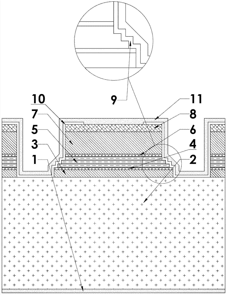
[0022] like figure 1 As shown, the structure of a quantum cascade laser with high-efficiency lateral heat conduction in the present invention is as follows from bottom to top: Au / Ge / Ni substrate surface electrode 1, N-type InP substrate 2, N-type InP lower cladding layer 3, N-type InGaAs lower waveguide layer 4, N-type InGaAs / InAlAs active region 5, N-type InGaAs upper waveguide layer 6, N-type InP upper cladding layer 7, N-type InP cap layer 8, Si 3 N 4 Electrical insulating layer 10 and Ti / Pt / Au epitaxial surface electrode 11. The number of steps in the stepped waveguide structure 9 is greater than or equal to one step, and in this embodiment, the number of steps is three steps. The height and...


PUM


Abstract

The invention discloses a quantum cascade laser structure with high-efficiency lateral heat conduction and a preparation method thereof. The laser adopts a stepped waveguide structure, that is, when the laser is working, the active area with severe heat generation is partially etched into a stepped mesa, so that the heat exchange area of ​​the heat generation area increases, which can effectively reduce the temperature of the active area and reduce the temperature of the active area. It can improve the shortcoming of poor current confinement caused by the traditional wet-etched double-channel ridge waveguide, reduce current leakage, and improve the electro-optical conversion efficiency of the laser. The invention can improve the output power, working stability and service life of the laser, reduce the pressure of temperature control equipment, and is suitable for the production of high-power quantum cascade laser single tube and array.

Description

technical field [0001] The invention belongs to the technical field of semiconductor optoelectronics, and mainly relates to a quantum cascade laser structure with high-efficiency lateral heat conduction and a preparation method thereof. Background technique [0002] In 1994, Bell Labs realized the lasing of quantum cascade lasers. Unlike traditional semiconductor lasers, quantum cascade lasers are unipolar devices that rely on electrons to transition in sub-bands to emit light. The lasing wavelength of the laser does not depend on Due to the bandgap width of the material, the energy band can be appropriately "cut" to obtain different lasing wavelengths without changing the material system, which has a great degree of freedom for laser design. [0003] Due to the high heat generation in the active region of quantum cascade lasers, even though the commonly used wet-etched double-channel ridge waveguide is better than the dry-etched double-channel ridge waveguide in terms of de...

Claims


Application Information

Patent Timeline
Patent Type & Authority Patents(China)
IPC IPC(8): H01S5/024H01S5/40
Inventor 佟存柱卢泽丰舒世立吴昊田思聪汪丽杰宁永强王立军
Owner 吉光半导体科技有限公司
Learn More