
Rapid etching device and method for printed circuit board of new energy automobile

A technology for new energy vehicles and printed circuit boards, which is applied in the fields of printed circuit, printed circuit manufacturing, and removal of conductive materials by chemical/electrolytic methods. It can solve the problems of increasing etching cost, reducing etching efficiency, and long etching time, etc. , to achieve the effect of speeding up the moving speed, improving the etching efficiency and simple operation

Active Publication Date: 2019-08-09
SICHUAN HAIYING ELECTRONICS TECH
View PDF4 Cites 1 Cited by
  • Summary
  • Abstract
  • Description
  • Claims
  • Application Information

AI Technical Summary

Problems solved by technology

The core process of the new energy vehicle printed circuit board manufacturing process is etching. The purpose is to remove the unnecessary copper foil to obtain the required circuit diagram. Among them, spray etching is the most commonly used. It sucks the etching liquid into the nozzle by pressurization. Then spray it on the surface of the circuit board, and the etching solution will corrode the unnecessary copper foil. During the etching, since a large amount of etching solution will remain on the surface of the etching solution, after the etching solution is taken out from the etching tank, part of the etching solution will be taken away. , leading to a decrease in the amount of etching solution in the etching tank, and to replenish new etching solution, thereby increasing the etching cost
In addition, during etching, workers need to put the printed circuit board into the etching tank for a period of time, and after etching for a period of time, the product can be taken out. However, this method has the disadvantage of long etching time, which reduces the etching efficiency

Method used


Image

  • Rapid etching device and method for printed circuit board of new energy automobile
  • Rapid etching device and method for printed circuit board of new energy automobile

Examples


Embodiment Construction

[0016] The present invention will be further described below in conjunction with accompanying drawing, protection scope of the present invention is not limited to the following:

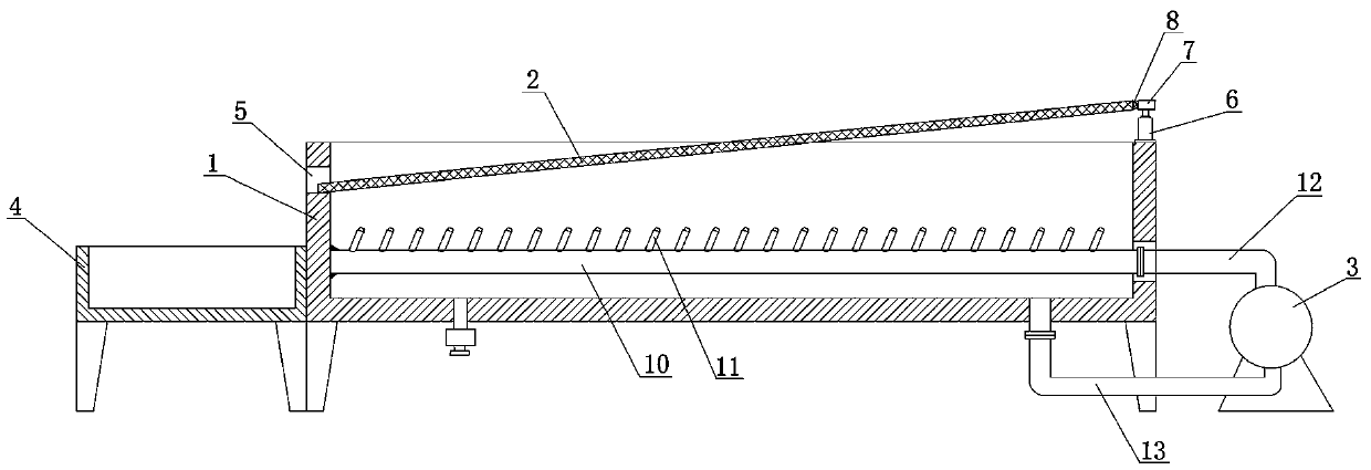
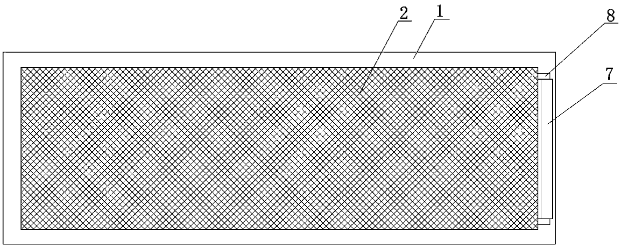
[0017] Such as Figure 1~2 As shown, the rapid etching device for printed circuit boards for new energy vehicles includes an etching tank 1, a filter screen 2, a water pump 3 and a circuit board collection tank 4, and a through groove 5 is provided on the left side wall of the etching tank 1 , the top of the right side wall of the etching groove 1 is fixedly equipped with a vertically arranged oil cylinder 6, the top of the piston rod of the oil cylinder 6 is welded with a support plate 7, the support plate 7 is provided with a hinge seat 8, and the filter screen 2 is inclined to the left Set downwards, the filter screen 2 is arranged on the top of the etching tank 1, the left edge of the filter screen 2 extends into the through groove 5, the right edge of the filter screen 2 is hinged on the hinge s...


PUM


Abstract

The invention discloses a rapid etching device for a printed circuit board of a new energy automobile. The device comprises an etching groove (1), a filter screen (2), a water pump (3) and a circuit board collecting tank (4), and a through groove (5) is formed in the left side wall of the etching groove (1). A vertically arranged oil cylinder (6) is fixedly mounted at the top of the right side wall of the etching groove (1), and a supporting plate (7) is welded to the top of a piston rod of the oil cylinder (6). A hinge seat (8) is arranged on the supporting plate (7), and the filter screen (2) is obliquely arranged downwards leftwards and is arranged above the etching groove (1). The left edge of the filter screen (2) extends into the through groove (5), and the right edge of the filter screen (2) is hinged to the hinge seat (8) through a pin shaft. A water outlet pipe (10) is welded in the etching groove (1) and located on the left side wall. The beneficial effects of the invention are that the structure is compact, the etching efficiency is greatly improved, the etching cost is greatly saved, and the operation is simple.

Description

technical field [0001] The invention relates to a rapid etching device and method for a printed circuit board used in a new energy vehicle. Background technique [0002] New energy vehicle printed circuit board is an important part of electric vehicle circuit unit, its design is mainly layout design; the main advantage of new energy vehicle printed circuit board is to greatly reduce wiring and assembly errors, improve automation level and production labor Rate. The core process of the new energy vehicle printed circuit board manufacturing process is etching. The purpose is to remove the unnecessary copper foil to obtain the required circuit diagram. Among them, spray etching is the most commonly used. It sucks the etching liquid into the nozzle by pressurization. Then spray it on the surface of the circuit board, and the etching solution will corrode the unnecessary copper foil. During the etching, since a large amount of etching solution will remain on the surface of the e...

Claims


Application Information

Patent Timeline
Patent Type & Authority Applications(China)
IPC IPC(8): H05K3/06
CPCH05K3/068
Inventor 王青木周顺建刘非
Owner SICHUAN HAIYING ELECTRONICS TECH
Learn More