

Buffering braking mechanism of electric injection molding machine
A brake mechanism and injection molding machine technology, applied in the field of buffer brake mechanism, can solve the problem of damage to the moving parts of the electric injection molding machine, etc., and achieve the effects of small space occupation, high adaptability, and convenient maintenance and modification
- Summary
- Abstract
- Description
- Claims
- Application Information
AI Technical Summary
Problems solved by technology
Method used
Image

Examples
Embodiment 1
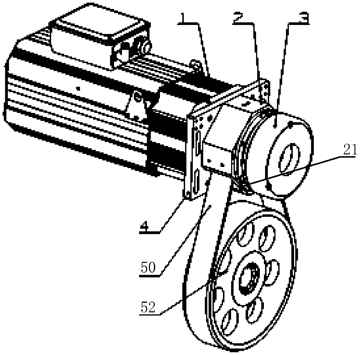
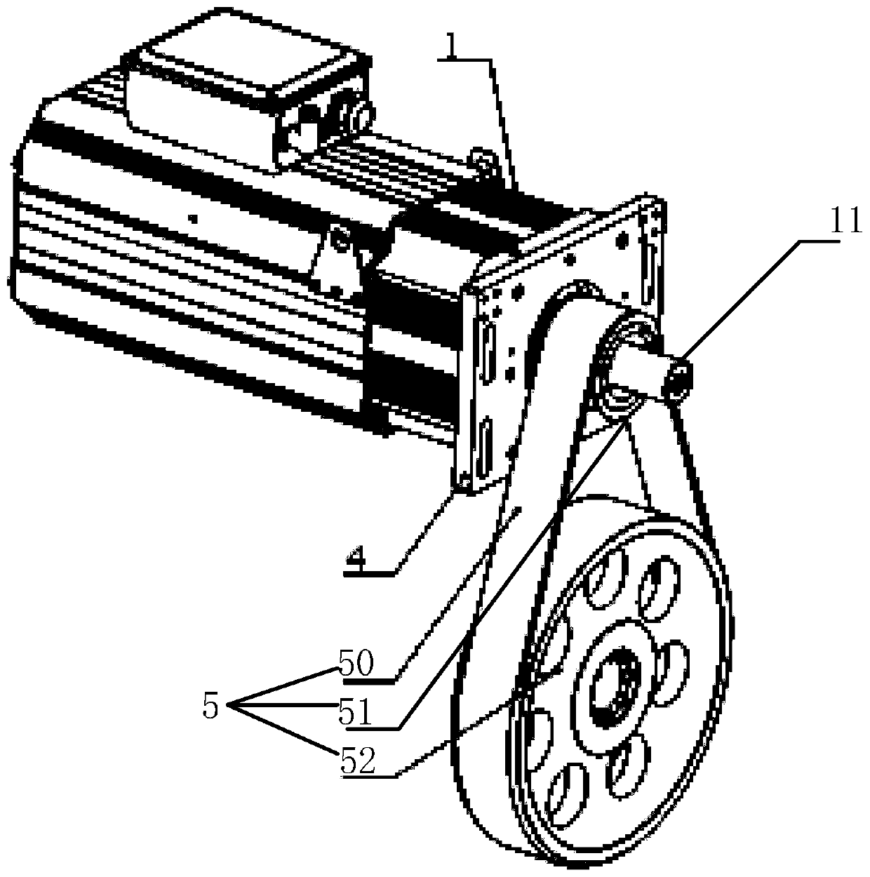
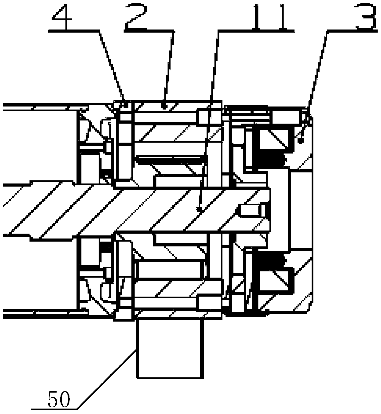
[0025] refer to Figure 1 to Figure 3 , this embodiment provides a buffer brake mechanism for an electric injection molding machine, including a servo motor 1, a fixing device 4, a connecting seat 2, a buffer brake device 3 and a transmission assembly 5;
[0026] The transmission assembly 5 includes a first pulley 51, a second pulley 52 and a transmission belt 50, and the first pulley 51 and the second pulley 52 are connected by the transmission belt 50;
[0027] The servo motor 1 and the connecting seat 2 are respectively fixed on the fixing device 4, and the buffer braking device 3 is fixed on the connecting seat 2 by screws;
[0028] The servo motor 1 is provided with an output shaft 11, the output shaft 11 passes through the fixing device 4, and is connected with the inner ring of the buffer braking device 3 through a flat key;
[0029] The first pulley 51 is sheathed on the output shaft 11 , and the second pulley 52 is provided with a screw rod, on which a screw nut is a...
PUM
 Abstract
Description
Claims
Application Information