Extreme environment resistant sapphire fiber bragg grating sensor and temperature detection method thereof

A fiber grating, sapphire crystal technology, applied in thermometers, thermometers, instruments, etc. with physical/chemical changes, can solve the problems of weak accident resistance, large equipment size and cable volume, and increased demodulation complexity, etc. Sensitivity, effect of effective temperature detection

Active Publication Date: 2019-08-13
UNIV OF ELECTRONICS SCI & TECH OF CHINA
View PDF4 Cites 2 Cited by
  • Summary
  • Abstract
  • Description
  • Claims
  • Application Information

AI Technical Summary

Problems solved by technology

[0003] At present, in the nuclear radiation environment, the existing process parameters are measured using traditional electrical sensors, which have defects such as large equipment size and cable volume, weak anti-electromagnetic interference ability, weak accident resistance ability, etc. It is difficult to achieve ideal results in areas related to process parameter measurement
Although some studies have shown the possibility of applying femtosecond-written quartz fiber FBG sensors in nuclear radiation environments, the existing fiber sensor products have not yet formed products that are truly suitable for extremely harsh environments with high radiation, high temperature, high pressure, and strong vibration. Fully meet the needs of safety monitoring in extremely harsh environments
In addition, so far, there is no sapphire single-mode fiber product, and the existing sapphire crystal fiber grating sensors are all fused with multimode fiber and sapphire crystal fiber, and then the writing of the grating on the sapphire crystal fiber is completed.
This technology uses multimode as the transmission fiber to increase the complexity of demodulation

Method used


Image

  • Extreme environment resistant sapphire fiber bragg grating sensor and temperature detection method thereof

Examples


Embodiment Construction

[0016] In order to facilitate those skilled in the art to understand the technical content of the present invention, the content of the present invention will be further explained below in conjunction with the accompanying drawings.

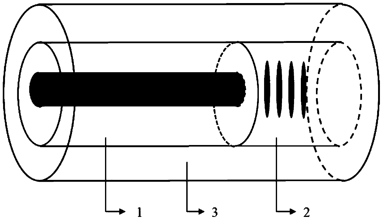
[0017] Such as figure 1 As shown, the sapphire crystal fiber grating temperature sensor includes a single-mode sensing fiber 1 , a sapphire crystal fiber grating 2 and a coating layer 3 . The production method is realized, and the specific steps are as follows:

[0018] A. Grinding one end of the sapphire crystal fiber to make the end face flat;

[0019] B. cutting the end face of the single-mode sensing fiber 2;

[0020] C. Splice the flattened section of the sapphire crystal fiber and the cut flat end face of the single-mode sensing fiber 2;

[0021] D. A fiber grating made by femtosecond laser point-to-point technology at the single-mode near-field position near the fusion point on the sapphire crystal fiber;

[0022] E. Coating materials ...


PUM


Abstract

The invention discloses an extreme environment resistant sapphire fiber bragg grating sensor and a temperature detection method thereof. In view of the problem of application of a temperature sensor under extreme conditions, the extreme environment resistant sapphire fiber bragg grating sensor comprises: performing fusion splicing on a sapphire crystal fiber with a flat section and a flatly cut single mode fiber, as well as engraving a grating at a single mode near field position on the sapphire crystal fiber close to a fusion splicing point, and coating a protective material at the outside ofthe grated sapphire crystal fiber and the single mode fiber to obtain a sapphire crystal fiber bragg grating temperature sensor; performing mode selection on the light transmitted to a sapphire crystal fiber bragg grating area through the single mode fiber, so that the light of only a few modes or a single mode is transmitted into the sapphire crystal fiber bragg grating area; and when the external temperature changes, the effective refractive index and the grating period of the sapphire crystal fiber bragg grating change, so that the center wavelength changes, and the external temperature change is obtained by demodulation by recording the center wavelength of the sapphire crystal fiber bragg grating.

Description

technical field [0001] The invention belongs to the technical field of optical fiber sensing, in particular to a sapphire crystal fiber grating temperature sensor resistant to extremely severe environments. Background technique [0002] For the measurement of process parameters in extremely harsh environments such as high radiation, high temperature, high pressure, and strong vibration, fiber optic sensors have emerged due to their outstanding advantages, such as natural insulation, not afraid of electromagnetic interference; simple structure, strong environmental tolerance; small size, Good flexibility, suitable for comprehensive layout of ships, can effectively reduce the space occupied by instruments; distributed layout can be used to improve the informatization and intelligence level of the measurement system. Therefore, fiber optic sensors have great potential advantages in the measurement of process parameters in extremely harsh environments. [0003] At present, in t...

Claims


Application Information

Patent Timeline
Patent Type & Authority Applications(China)
IPC IPC(8): G01K11/32G01K11/3206
CPCG01K11/3206
Inventor 冉曾令李卓玥饶云江
Owner UNIV OF ELECTRONICS SCI & TECH OF CHINA
Why Eureka
Try Eureka