Preparation method of field-effect electrocatalytic hydrogen production device

An electrocatalysis and field effect technology, applied in the field of nanomaterials and electrochemistry, can solve the problems of rare research on the influence of catalytic reactions, and achieve the effects of optimizing the electrocatalytic performance of nanomaterials, optimizing the catalytic performance of materials, and accurate testing and characterization.

Active Publication Date: 2018-09-18
WUHAN UNIV OF TECH
View PDF8 Cites 0 Cited by
  • Summary
  • Abstract
  • Description
  • Claims
  • Application Information

AI Technical Summary

Problems solved by technology

However, electrocatalysis is a reaction that occurs at the interface between materials and solutions, and the influence of the state of the surface interface on the catalytic reaction is rarely studied.

Method used


Image

  • Preparation method of field-effect electrocatalytic hydrogen production device
  • Preparation method of field-effect electrocatalytic hydrogen production device
  • Preparation method of field-effect electrocatalytic hydrogen production device

Examples


Embodiment 1

[0025] The preparation method of the field effect electrocatalytic hydrogen production device of the present invention, it comprises the steps:

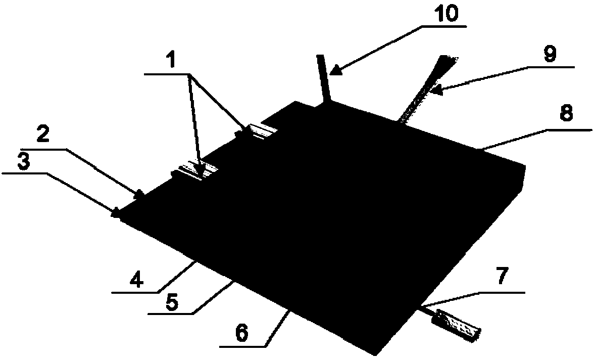
[0026] 1) VSe prepared by mechanical exfoliation 2 The nano flakes 6 are dispersed onto a clean silicon substrate 3 with an oxide layer (the oxide layer is 300nm SiO 2 layer) surface, where the nanoflakes serve as the channel material, and the oxide layer serves as the dielectric layer 2.

[0027] 2) Metal microelectrodes arranged in parallel on both ends of the nanosheet 6 are fabricated as the working electrode 1 (Cr 5nm, Au 150nm) by means of electron beam exposure etching and physical thermal evaporation deposition.

[0028] 3) Spin-coat a layer of polymethyl methacrylate (PMMA) (thickness 1.6 μm) as the insulating layer 4, and use electron beam exposure and etching to etch a rectangular window parallel to the metal microelectrode at the position of the nanosheet 5. The channel material is exposed and the metal electrodes are c...

Embodiment 2

[0034] The method for testing the electrocatalytic performance optimization mechanism of nanosheets in the present invention, it comprises the steps:

[0035] 1) Select a clean heavily doped silicon substrate 3, and deposit 80nm Al on its surface using an atomic layer deposition system 2 o 3 as the dielectric layer 2.

[0036] 2) VSe prepared by mechanical exfoliation 2 The nano flakes 6 are dispersed on the surface of the silicon substrate 3 with an oxide layer.

[0037] 3) using electron beam exposure etching and physical thermal evaporation deposition on both ends of the nanosheet 6 (in contact with the nanosheet) and the outer side (not in contact with the nanosheet) and one side edge of the silicon substrate (the area where the oxide layer is removed) Metal microelectrodes (Cr 5nm, Au 150nm) were fabricated as the working electrode 1, the counter electrode 10 and the back gate electrode 7 respectively.

[0038] 4) Spin-coat a layer of PMMA with a thickness of 1.6 μm a...

Embodiment 3

[0045] In the present invention, the method for in-situ testing the influence of ion distribution on the electrical transport properties of materials in the electrocatalytic process of nanosheets comprises the following steps:

[0046] 1) VSe prepared by mechanical exfoliation 2 Nanoflakes 6 are dispersed onto a clean silicon substrate 3 with an oxide layer 2 (the surface is 300nm SiO 2 layer) surface, where the nanoflakes serve as the channel material, and the oxide layer serves as the dielectric layer 2.

[0047] 2) Metal microelectrodes 1 (Cr 5nm, Au 150nm) arranged in parallel are fabricated on both ends of the nanosheet 6 by means of electron beam exposure etching and physical thermal evaporation deposition.

[0048] 3) Spin-coat a layer of PMMA with a thickness of 1.6 μm as the insulating layer 4, and use electron beam exposure and etching to etch a rectangular window 5 parallel to the metal microelectrode at the position of the nanosheet 6, so that the channel material i...


PUM

PropertyMeasurementUnit
thicknessaaaaaaaaaa
thicknessaaaaaaaaaa

Abstract

The invention relates to a preparing method for a field effect electro-catalysis hydrogen production device. At least one layer of VSe2 nano sheet is dispersed to a silicon substrate with an oxide layer, wherein the nano sheet serves as a channel material, the oxide layer serves as a dielectric layer, and metal micro electrodes are manufactured at the two ends of the channel material; spin coating of an insulation layer is conducted, and a rectangular window is etched between the two metal micro electrodes; and the oxide layer is removed from the blank side of the silicon substrate, a contact point of a back gate electrode is manufactured, and an electrolyte is injected to the surface of the device to obtain the field effect electro-catalysis hydrogen production device. The preparing method has the beneficial effects that the preparing method can serve as the new strategy for optimizing the electro-catalysis performance of nano materials.

Description

technical field [0001] The invention belongs to the technical field of nanometer materials and electrochemistry, and in particular relates to a preparation method of a field-effect electrocatalytic hydrogen production device. Background technique [0002] Hydrogen energy is known as the cleanest energy in the 21st century, and it has broad application prospects due to its abundant resources, renewability, and high energy density. Under the background of the current emphasis on environmental protection, the development of hydrogen energy is particularly important. There are many ways to produce hydrogen, such as fossil fuel hydrogen production, microbial hydrogen production, photocatalytic hydrogen production and electrolysis of water hydrogen production. Among them, hydrogen production by electrolysis of water is the most efficient and feasible hydrogen production method and has been widely used. However, traditional precious metals such as platinum and palladium are excel...

Claims


Application Information

Patent Timeline
Patent Type & Authority Patents(China)
IPC IPC(8): C25B11/06C25B11/02C25B1/04B82Y30/00B82Y40/00
CPCB82Y30/00B82Y40/00C25B1/04C25B11/02C25B11/059C25B11/091Y02E60/36
Inventor 麦立强潘雪雷晏梦雨王俊辉
Owner WUHAN UNIV OF TECH
Why Eureka
Try Eureka