LED driving circuit based on double PWM signals, LED lighting device, and driving method

A PWM signal, LED driving technology, applied in the field of LED lighting, can solve the problems of increased defective product rate, increased conductive wire, increased operation, etc., and achieves the effect of high practical significance and simple structure

Pending Publication Date: 2019-08-13
魏幸强
View PDF0 Cites 3 Cited by
  • Summary
  • Abstract
  • Description
  • Claims
  • Application Information

AI Technical Summary

Problems solved by technology

Each additional drive circuit in the LED module will inevitably lead to the addition of more conductive wires
This makes it necessary to reserve space for more conductive wires in the actual assembly process of miniaturized LED products, and it will also increase the number of operations in the assembly process.
In addition, more conductive wires will also lead to an increase in the rate of defective products due to improper operation of workers, and during actual transportation or use of LED products, if the LED product is placed in a vibration or shaking environment for a long time, the welding points of the conductive wires will loosen and cause damage. The probability of failure will also increase

Method used


Image

  • LED driving circuit based on double PWM signals, LED lighting device, and driving method
  • LED driving circuit based on double PWM signals, LED lighting device, and driving method

Examples


Embodiment Construction

[0020] The following will clearly and completely describe the technical solutions in the embodiments of the present invention. Obviously, the described embodiments are only some of the embodiments of the present invention, rather than all the embodiments. Based on the embodiments of the present invention, all other embodiments obtained by persons of ordinary skill in the art without making creative efforts belong to the protection scope of the present invention.

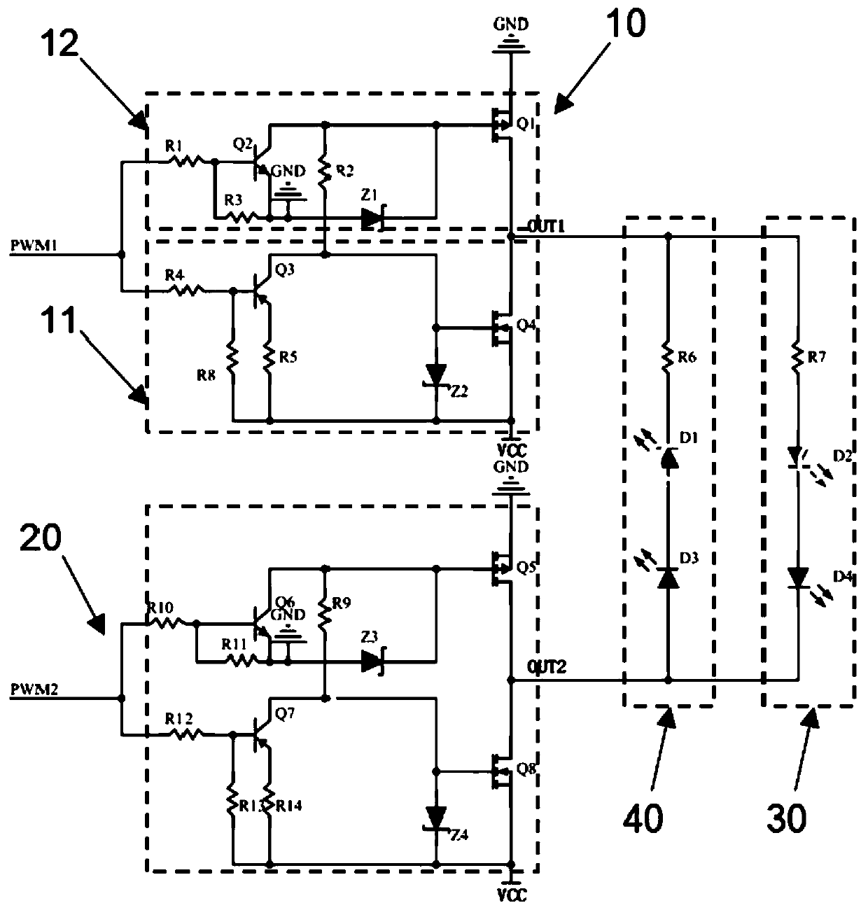
[0021] like figure 1 As shown, the present invention provides an LED drive circuit based on dual PWM signals, including: a first PWM signal input terminal PWM1, a first PWM signal input terminal PWM2, a first electrode switching circuit 10, a second electrode switching circuit 20, a first An LED lamp group 30 and a second LED lamp group 40 .

[0022] In this embodiment, the first PWM signal input terminal PWM1 is used to receive the first PWM signal; the second PWM signal input terminal PWM2 is used to receive the s...


PUM


Abstract

The invention provides an LED driving circuit based on double PWM signals, an LED lighting device, and a driving method. The LED driving circuit comprises a first PWM signal input end, a second PWM signal input end, a first electrode switching circuit and a second electrode switching circuit; a first LED lamp group, wherein the anodes of all the LED lamp beads in the first LED lamp group are connected with the first electrode end, and the cathodes of all the LED lamp beads in the first LED lamp group are connected with the second electrode end of the second electrode switching circuit; a second LED lamp group, wherein the cathodes of all the LED lamp beads in the second LED lamp group are connected with the first electrode end, and the anodes of all LED lamp beads in the second LED lamp group are connected with the second electrode end. After a first PWM signal and a second PWM signal are inputted, the electrode output by the first electrode end is opposite to the electrode output by the second electrode end, and the first LED lamp group or the second LED lamp group is turned on.

Description

technical field [0001] The invention relates to the technical field of LED lighting, in particular to an LED driving circuit based on dual-channel PWM signals, an LED lighting device and a driving method. Background technique [0002] LED is called the fourth-generation light source, which has the characteristics of energy saving, environmental protection, safety, long life, low power consumption, high brightness, miniature, shockproof, easy dimming, concentrated beam, and easy maintenance. It can be widely used in various indications, Display, decoration, backlight, general lighting and other fields. [0003] By dimming the LEDs, various light effects can be achieved to meet the requirements of different users in different situations. For example, the LED module is designed to emit two or three colors of light, and users can choose the corresponding color of light in different application scenarios. [0004] However, if the LED module is designed to emit light of multiple...

Claims


Application Information

Patent Timeline
IPC IPC(8): H05B33/08H05B44/00
CPCH05B45/00Y02B20/30
Inventor 魏幸强
Owner 魏幸强
Why Eureka
Try Eureka