
Visible side-guided tracheal tube member

A tracheal tube and guided technology, which is applied in the field of combined visible side-guided tracheal tube kits, can solve the problems of inconvenient operation, difficult positioning of the tube, and high cost of use, achieving simple tube placement and positioning, and wide application range wide effect

Pending Publication Date: 2019-08-16
上海兰甲医疗科技有限公司
View PDF1 Cites 3 Cited by
  • Summary
  • Abstract
  • Description
  • Claims
  • Application Information

AI Technical Summary

Problems solved by technology

[0005] 1) The total tube diameter is thick, the texture is relatively hard, the relative damage to the trachea and tissues is large, and the irritation is strong
[0006] 2) Can not be used for a long time
If the patient needs to continue respiratory support after the operation, the catheter is often removed and replaced with a single-lumen endotracheal catheter, and the replacement process not only increases tissue damage, but also may cause other accidents due to the difficulty of re-intubation
[0007] 3) During the operation, due to body position changes and surgical operations, sometimes the position of the catheter will shift and slip out of the bronchi, making it difficult to adjust the position, which will affect the ventilation method required by the operation and increase the difficulty of the operation
[0008] 4) The operation of intubation positioning has certain technical difficulties, and the precise positioning still depends on the fiberoptic bronchoscope
[0010] 1) It is difficult to accurately place the target bronchus, and it is necessary to use a bronchoscope to accurately locate it
[0011] 2) It takes a long time to complete the tube placement and it is easy to slip off with body position changes, and it is difficult to position the tube again after slipping off
[0012] 3) The application of anesthesia in right thoracic surgery is often limited
[0013] 4) There are problems of complex manufacturing process and high cost
The main problem is that the camera is placed in the lumen, so that the inner diameter of the distal end of the endotracheal tube is significantly narrowed, which not only affects the normal ventilation, but after the occlusion tube is inserted through this tube, due to the limitation of the lumen, it is necessary to place it again. It is very difficult to suction endotracheal secretions through the suction tube; although the tube is placed in the trachea to observe the position of the occluded tube, to ensure that the view of the lens is not blocked by the tube wall, the wall at the distal end of the endotracheal tube is flush with the lens , when the endotracheal tube is placed into the trachea, the structure of the distal flat head is easily blocked by the tracheal cartilage ring, which makes tube placement difficult; since there is no direction guidance, the positioning of the occlusion tube when it is placed into the target bronchi is required. Long time, inconvenient operation
Coupled with the existing plugging tubes used in the market, the cost of using both is also very high
[0016] 2) The applicant applied for an invention patent on July 25, 2017 "Combined side-guided tracheal and bronchial tube" (CN107261285A), the side-guided tracheal tube blocking tube set, and the blocking tube used in conjunction with it It is also a simple and elongated thin endotracheal tube. Although the insertion of the target bronchus is very simple and accurate, the accuracy of the insertion depth still needs to be confirmed by a fiberoptic bronchoscope, and it is not easy to use
1) and 2) also have the common disadvantage that the use of endoluminal lenses and bronchofiberoscopes requires the endotracheal tube to have a large enough caliber so as not to affect ventilation and operation

Method used


Image

  • Visible side-guided tracheal tube member
  • Visible side-guided tracheal tube member
  • Visible side-guided tracheal tube member

Examples


Embodiment Construction

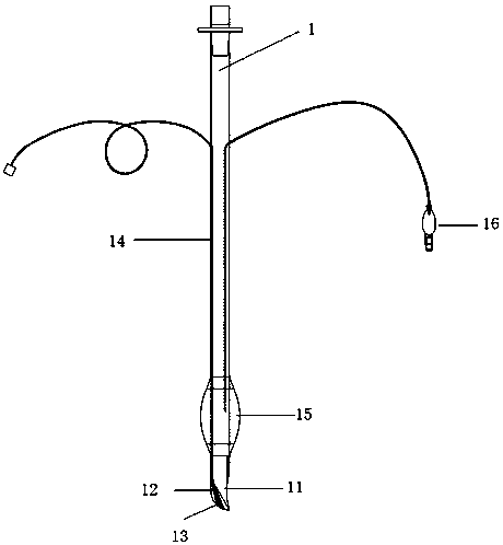
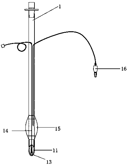
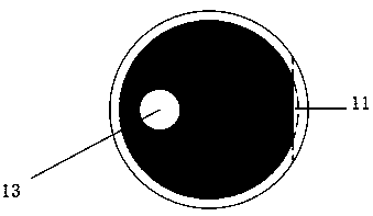
[0042]As shown in Fig. 1(A), Fig. 1(B) and Fig. 1(C), the visible side-guided endotracheal tube set according to the present invention mainly includes a visible side-guided endotracheal tube 1, a bronchial blocker Tube 2. The bronchial occlusion tube 2 can be inserted from the upper end of the visible side-guiding endotracheal tube 1 , and can be drawn out from the side opening 11 that enables the lower end of the side-guiding endotracheal tube 1 . The upper end of the visible lateral guided endotracheal catheter 1 is the machine end, and the lower end is the patient end. There is a side opening 11, and the opposite side tube wall at the side opening 11 is an arc-shaped side wall 12, and the opening direction of the side opening 11 is perpendicular to the longitudinal axis of the lumen of the visible side-guided endotracheal tube 1, pointing to The side, its structure is like a curved tube, the inner side after bending is cut along the endotracheal tube wall of this side to f...


PUM

PropertyMeasurementUnit
Lengthaaaaaaaaaa
Diameteraaaaaaaaaa

Abstract

The invention discloses a visual side-guided tracheal tube member. The upper side of the visible side-guided tracheal tube member is a machine end, the lower end is a patient end, the visible side-guided tracheal tube member is provided with an air bag near the wall of the patient end, an axially closed lateral opening is arranged at the tube wall at one side of the lower end of the air bag, the opening direction of the lateral opening is perpendicular to the longitudinal axis of the chamber of the tracheal tube, and laterally directed to the side surface; the tube wall of the lateral openingis a curved lateral-bending side wall, and a micro camera is disposed in the curved lateral-bending side wall. The process of feeding the tracheal tube into the bronchus by means of the equipment canbe observed through the longitudinal micro camera on the side wall of the lateral opening by a display connected thereto. The proper position and depth of the occlusion tube in the bronchus are clearly located to meet the clinical choice and usage of left and right lung isolation and single lung ventilation. The visual side-guided tracheal tube member makes the placement and positioning of the tracheal tube simple, accurate and reliable.

Description

technical field [0001] The invention relates to a trachea and bronchus tube, in particular to a combined visible side-guided trachea tube set. It is mainly suitable for anesthesia in thoracic surgery, etc., and can provide a simple, effective and reliable technique for double-lung isolation and single-lung ventilation. Background technique [0002] One-lung ventilation can provide lung isolation and facilitate surgical field exposure and intraoperative respiratory management. There are three types of lung isolation technology devices commonly used to provide one-lung ventilation: 1. Double lumen endobronchial tube (DLT), 2. Bronchial obstructor (BB), and 3. Single lumen endobronchial tube (ET). ET was widely used in early thoracic surgery, but with the development of the first two techniques, ET has been gradually eliminated. [0003] The two technical devices commonly used today still have different limitations. [0004] Double-lumen endobronchial tube (DLT) has the foll...

Claims


Application Information

Patent Timeline
IPC IPC(8): A61M16/04A61B1/267A61B1/04
CPCA61M16/04A61M16/0404A61M16/0429A61B1/2676A61B1/04A61M2210/1035A61M2210/005
Inventor 傅国强王剑陈文婷王永强
Owner 上海兰甲医疗科技有限公司
Learn More