Mixing device for soil remediation

A soil remediation and mixing device technology, which is applied in the field of soil remediation, can solve problems such as poor mixing effect and limited repair effect, and achieve the effect of avoiding screen hole clogging and improving crushing precision

Pending Publication Date: 2019-08-16
王晶晶
View PDF13 Cites 6 Cited by
  • Summary
  • Abstract
  • Description
  • Claims
  • Application Information

AI Technical Summary

Problems solved by technology

[0003] In the traditional leaching method, due to the agglomeration of the soil, it is difficult to make the soil fully contact with the soil remediation solution, resulting in poor mixing effect and limited remediation effect

Method used


Image

  • Mixing device for soil remediation
  • Mixing device for soil remediation
  • Mixing device for soil remediation

Examples


Embodiment 1

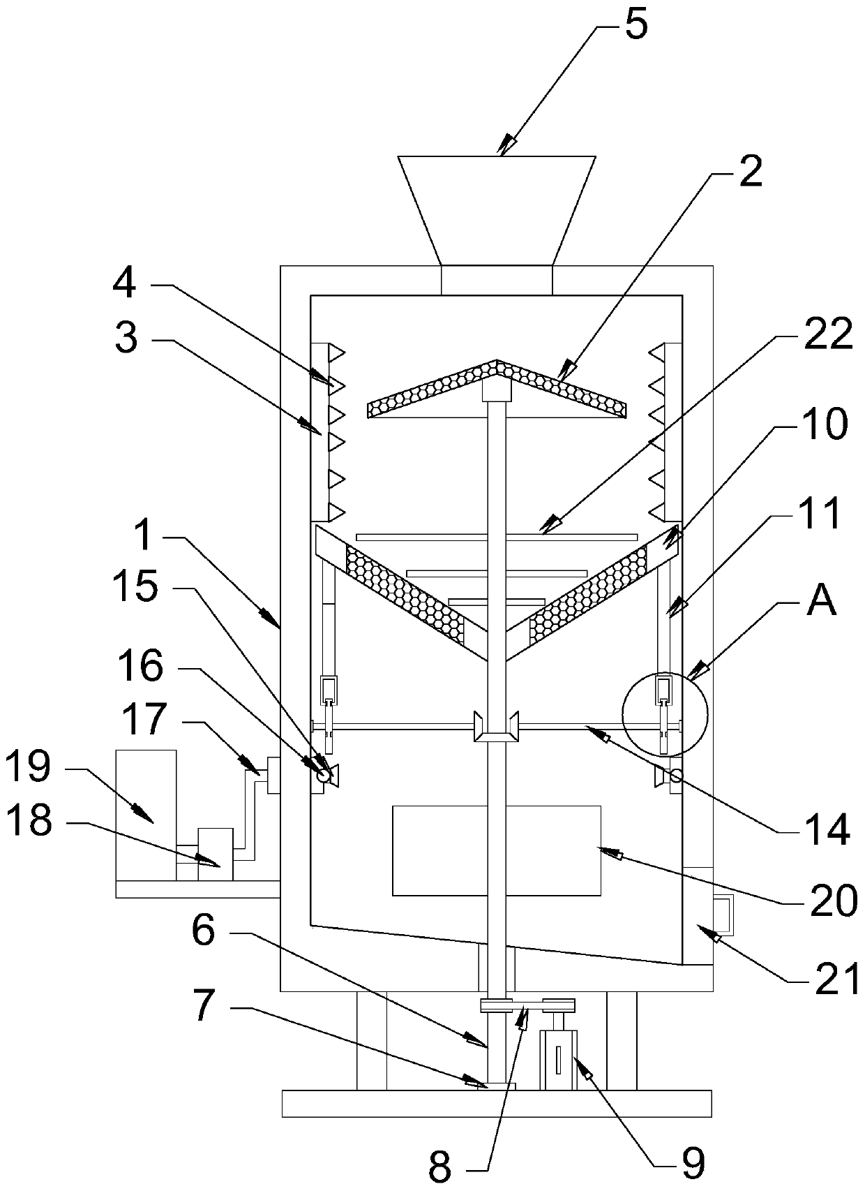
[0021] see Figure 1-4 , in an embodiment of the present invention, a soil remediation mixing device includes a box body 1; the upper end of the box body 1 is connected with a feed hopper 5; Cylinder 2 is a conical cylinder with sieve holes on the conical surface; an impact cylinder 3 is provided on the outside of the convex screen cylinder 2, and the impact cylinder 3 is fixedly connected with the inner wall of the box body 1, and the inner wall of the impact cylinder 3 is fixedly connected with a uniform Distributed impact teeth 4; the lower end of the convex screen cylinder 2 is fixedly connected with a central shaft 6, the central shaft 6 extends to the bottom of the box body 1, the central shaft 6 is rotationally connected with the base through the main bearing seat 7, and the central shaft 6 passes through the transmission The belt 8 is connected to the output shaft of the driving motor 9, and the driving motor 9 drives the central shaft 6 to rotate, and then drives the ...

Embodiment 2

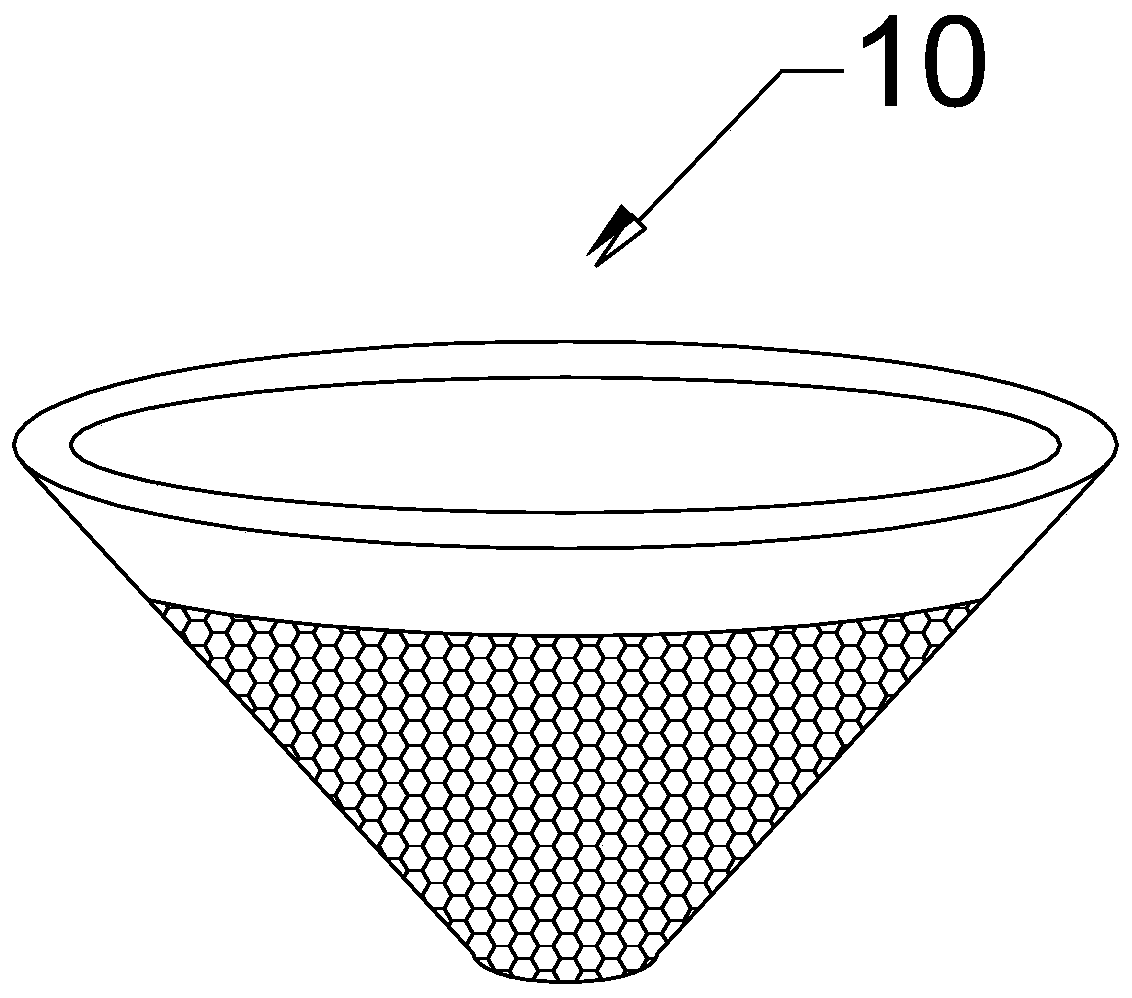
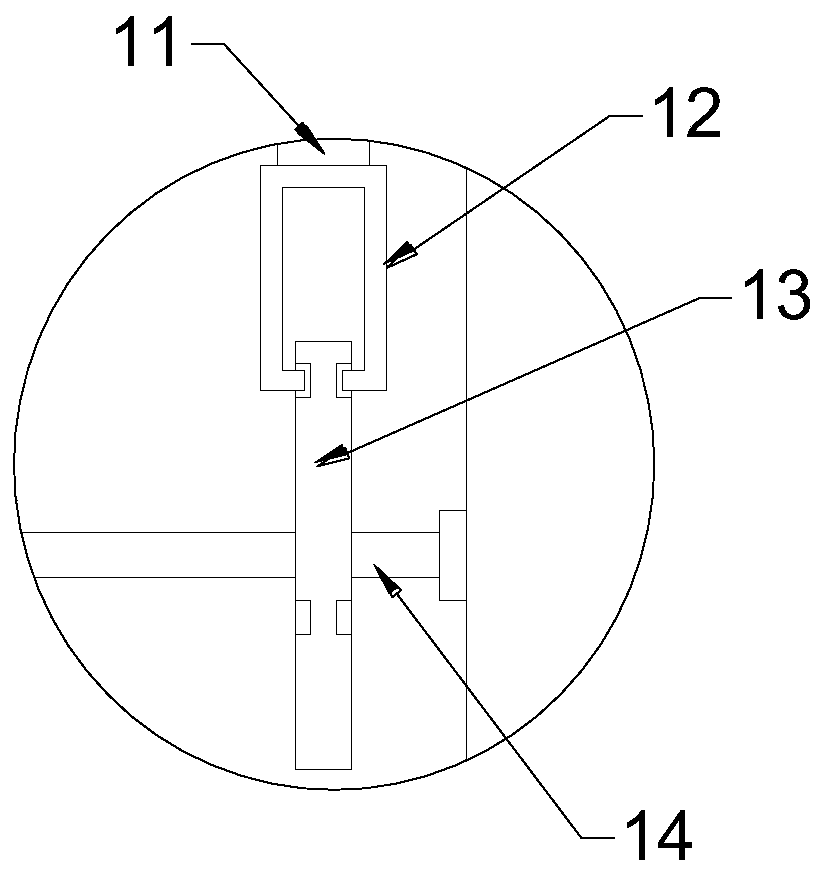
[0024] The difference between this embodiment and Embodiment 1 is that: the convex screen cylinder 2 is provided with a convex screen cylinder 10, and the convex screen cylinder 10 is a conical cylinder with evenly distributed sieve holes on the conical surface. And the tip of the tapered cylinder is facing downward; the edge of the convex screen cylinder 10 is fixedly connected with a connecting rod 11, and the lower end of the connecting rod 11 is fixedly connected with a clamping frame 12, and the clamping frame 12 is clamped with an eccentric disc 13, and the eccentric disc 13 is provided with a circular groove, and the lower end of the clamping frame 12 is nested in the circular groove and is slidably connected with the circular groove; the eccentric disc 13 is fixedly connected with a transmission shaft 14, and the transmission shaft 14 is rotationally connected with the inner wall of the box body 1. The inner side of the transmission shaft 14 is connected with the centra...


PUM


Abstract

The invention discloses a mixing device for soil remediation. The device comprises a box body; the upper end of the box body communicates with a material inlet hopper; and the interior of the box bodyis provided with an upwards-convex screen cylinder, the outer side of the upwards-convex screen cylinder is provided with an impact cylinder, the impact cylinder is fixedly connected with the inner wall of the box body, and the inner wall of the impact cylinder is fixedly connected with uniformly-distributed impact teeth. According to the device provided by the invention, the upwards-convex screen cylinder and the impact cylinder are arranged, so that soil is centrifugally screened, intercepted bulges are centrifugally thrown out, and crushing of the bulges is realized by cooperation of the upwards-convex screen cylinder and the impact cylinder; and a downwards-convex screen cylinder, connecting rods, clamping connection frames, eccentric disks and crushing blades are arranged, so that up-and-down movement of the downwards-convex screen cylinder is realized, the soil is further crushed by the crushing blades, clogging of screen holes is avoided, the crushing precision is improved, andsubsequent cooperation with a soil remediation liquid is facilitated.

Description

technical field [0001] The invention relates to the field of soil restoration, in particular to a mixing device for soil restoration. Background technique [0002] The soil is originally a natural shelter and purification treatment place for various wastes. The soil accepts pollutants, which does not mean that the soil is polluted. Only when the soil contains too many pollutants, it affects and exceeds the self-purification ability of the soil. , thus producing harmful hygienic and epidemiological effects, which indicate that the soil has been polluted. There are many reasons for soil pollution, such as industrial sludge, agricultural garbage, sewage irrigation, pollutant deposition in the atmosphere, heavy use of mineral fertilizers and pesticides containing heavy metals, and so on. Chemical leaching, with the help of chemical / biochemical solvents that can promote the dissolution or migration of pollutants in the soil environment, the eluent is injected into the contaminat...

Claims


Application Information

Patent Timeline
IPC IPC(8): B09C1/02B02C18/12B02C23/16B02C19/00
CPCB02C18/12B02C19/0018B02C23/16B09C1/02
Inventor 王晶晶
Owner 王晶晶
Why Eureka
Try Eureka