Electromagnetically driven braided fabric pulling device

A pulling device and knitted fabric technology, applied in weft knitting, warp knitting, knitting and other directions, can solve the problems of increased scrap rate, loss of rubber layer, easy deformation of knitted fabric, etc. And the effect of easy maintenance, easy installation and disassembly

Pending Publication Date: 2019-08-16
TONGXIANG JUXING KNITTING MACHINERY MFGCO
View PDF0 Cites 4 Cited by
  • Summary
  • Abstract
  • Description
  • Claims
  • Application Information

AI Technical Summary

Problems solved by technology

[0002] At present, most of the pulling devices of knitting machines use roller devices, but the roller devices pull the braided fabric at the same time as a whole rotating motion. The pulling force depends on the rotation speed of the rollers and the surface friction of the rubber layer of the rollers, which cannot be realized. The pulling force is precisely controlled, and it is impossible to achieve selective partial pulling of the braid, and the rubber layer in the roller has a certain weariness, and the braid will be easily deformed when pulled to a certain extent, increasing the scrap rate, especially On knitting, wearable and fully formed machines, the pulling of a single layer of cloth cannot be realized because two layers of cloth are clamped in the rollers at the same time, and the local pulling of the cloth cannot be realized, so it cannot be used

Method used


Image

  • Electromagnetically driven braided fabric pulling device
  • Electromagnetically driven braided fabric pulling device
  • Electromagnetically driven braided fabric pulling device

Examples


Embodiment 1

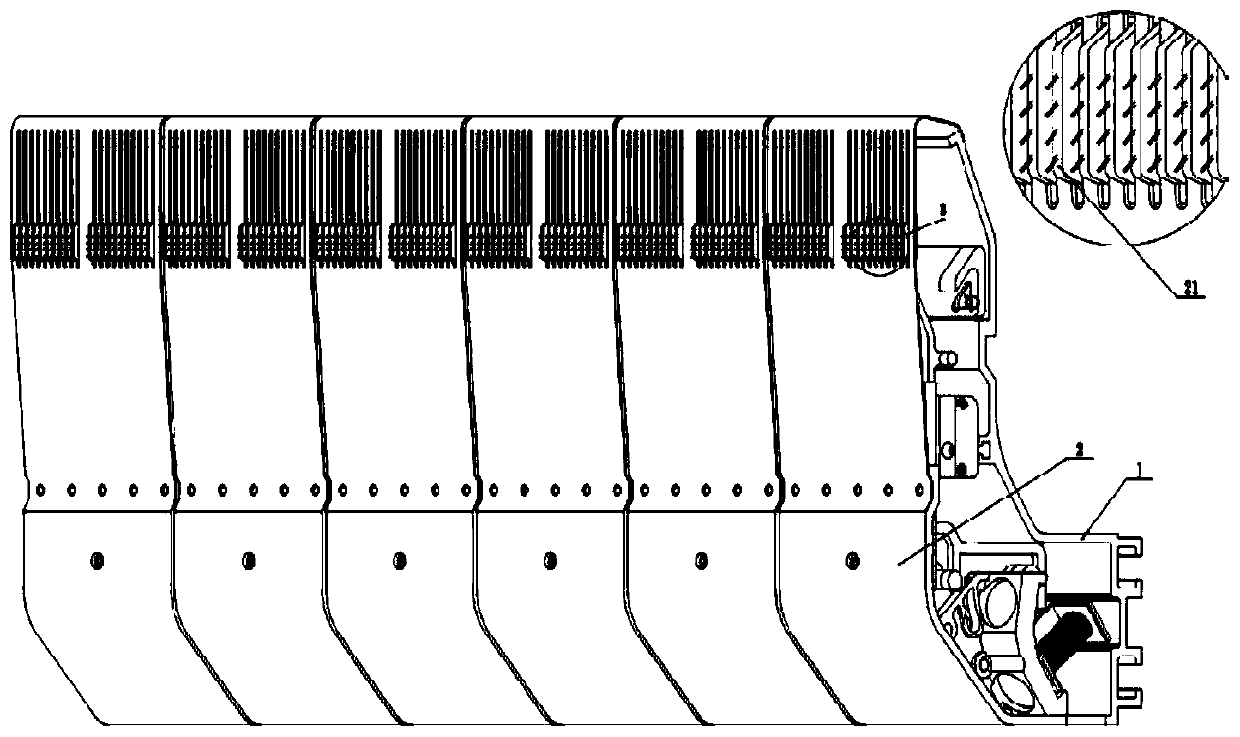
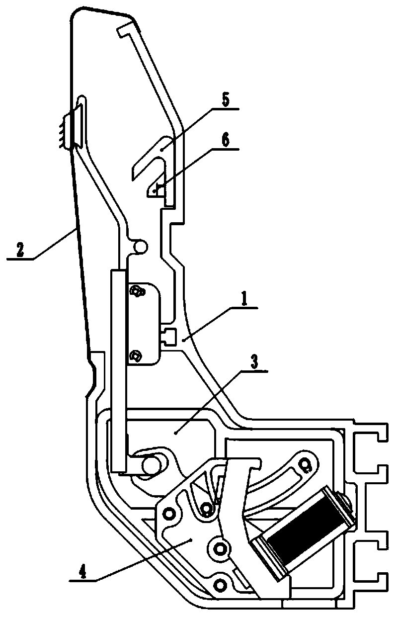
[0024] Such as figure 1 , 2 As shown, the present invention provides an electromagnetically driven braid pulling device, including a housing, a driving module, and a lifting module, wherein the driving module and the lifting module are all connected to the housing 1, and the driving module is connected to the lifting module through a push-pull rod. Connected, the drive module changes the current through the electromagnet to produce a position change between the permanent magnet groups, driving the push-pull rod 11 to move up and down; thus driving the slide rail in the lifting module to move up and down, the upper end of the slide rail is connected to the needle claw 21, and the needle claw moves up and down Complete the pull.

[0025] Preferably, as Figure 7 As shown, several pulling devices are arranged in pairs under the needle bed with claws facing each other, A1 pulls the fabric 103 knitted by the front needle bed 101, and A2 pulls the fabric 104 knitted by the rear ne...

Embodiment 2

[0027] driver module

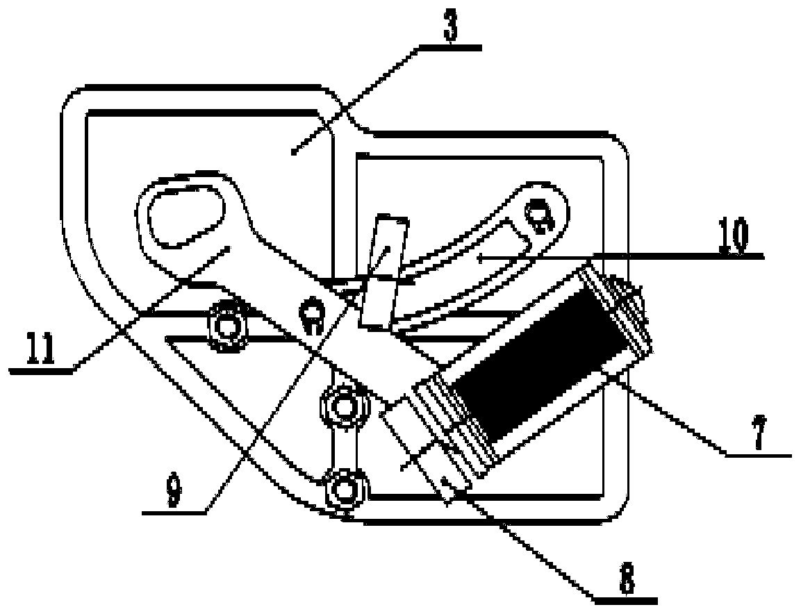
[0028] image 3 , Figure 4 It is a structural diagram of the drive module in the embodiment of the present invention. As shown in the figure, the drive module includes a support plate 3, an upper link 10, a lower link 12, a push-pull rod 11, an electromagnet 7 and a permanent magnet group. The support plate is fixed in the housing, the tail ends of the upper link and the lower link are respectively connected to the support plate through the rotation axis B14 and the rotation axis A13, and the push-pull rod is respectively connected with the upper link and the lower link by the rotation axis C15 and the rotation axis D16. The head end of the bar is connected, the electromagnet is fixed on the lower connecting rod, and the permanent magnet group is arranged at the electromagnet rear, is made up of upper and lower permanent magnets A8 and permanent magnets B9 whose magnetism is opposite, and is fixed on the magnet seat 4.

[0029] When the electromagnet ...

Embodiment 3

[0033] lift module

[0034] Such as Figure 5 , Figure 6 As shown, the pulling mechanism includes the needle claw 21, the needle claw seat 20, the slide rail 17, and the bearing seat 23 connected sequentially from top to bottom. A bearing B22 is provided in the middle of the needle claw seat, and a chute is provided on the slide rail. A slide block 18 is connected in the chute, and the swing block 27 is fixedly connected to the slide block. The swing block is connected with the swing seat 19 through the rotating shaft E25 and the limit shaft F26, and the bearing seat is provided with a bearing A24. The bearing A is connected to the drive. In the control slot on the push-pull rod of the module.

[0035] The pulling device is also provided with a baffle plate 2, which is fixed on the outer side of the needle claw seat on the housing, and a plurality of grooves for the needle claws to pass are arranged on the baffle plate.

[0036] When the slide rail 17 is under force, it ca...


PUM


Abstract

The invention provides an electromagnetically driven braided fabric pulling device. The device comprises a casing, a drive module and a lifting module, wherein the drive module and the lifting moduleare connected onto the casing, the drive module is connected with the lifting module through a push-pull rod, the drive module changes current through an electromagnet to produce position change in apermanent magnet group to drive the push-pull rod to move up and down, so that a slide rail in the lifting module to move up and down, the upper end of the slide rail is connected with a needle claw,and the needle claw moves to complete pulling. The provided electromagnetically driven braided fabric pulling device is simple and flexible due to a modular design structure, can pull any position ofbraided fabric and can accurately control and adjust pulling force.

Description

technical field [0001] The invention relates to the technical field of knitting machinery, in particular to an electromagnetically driven braid pulling device. Background technique [0002] At present, most of the pulling devices of knitting machines use roller devices, but the roller devices pull the braided fabric at the same time as a whole rotating motion. The pulling force depends on the rotation speed of the rollers and the surface friction of the rubber layer of the rollers, which cannot be realized. Precise control of the pulling force makes it impossible to achieve selective partial pulling of the braid, and the rubber layer in the roller has a certain degree of loss, and the braid will be easily deformed when pulled to a certain extent, increasing the scrap rate, especially On the knitting and wearing and fully formed machines, the pulling of a single layer of cloth cannot be realized because the two layers of cloth are clamped in the rollers at the same time, and ...

Claims


Application Information

Patent Timeline
Patent Type & Authority Applications(China)
IPC IPC(8): D04B15/88D04B15/99D04B27/34
CPCD04B15/88D04B15/99D04B27/34
Inventor 蒋瑞荣李先彦
Owner TONGXIANG JUXING KNITTING MACHINERY MFGCO
Why Eureka
Try Eureka