Air-conditioning haze control device and method

An air conditioning and smog technology, applied in the direction of fog removal, cleaning methods, buildings, etc., can solve the problem of easy accumulation of smog, and achieve the effect of speeding up air flow, improving air circulation speed, and improving the effect of haze removal.

Pending Publication Date: 2019-08-16
POWERCHINA XIBEI ENG
View PDF0 Cites 0 Cited by
  • Summary
  • Abstract
  • Description
  • Claims
  • Application Information

AI Technical Summary

Problems solved by technology

[0005] The purpose of the present invention is to solve the problem of easy accumulation of smog in cities with basin topography, and provide a device and method that can drive air circulation, especially an air-conditioning smog control device and method

Method used


Image

  • Air-conditioning haze control device and method
  • Air-conditioning haze control device and method

Examples


Embodiment 1

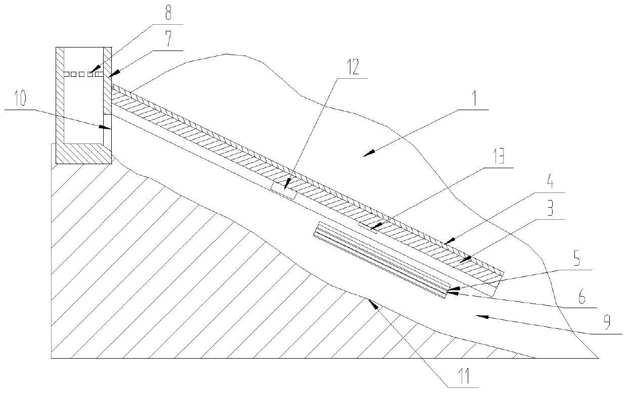
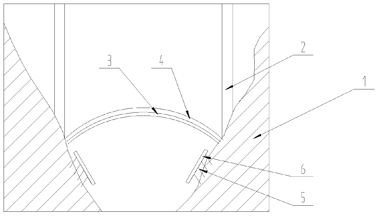
[0029] refer to Figure 1~2 , is a structural schematic diagram of Embodiment 1 of the present invention, an air-conditioning haze control device, at least including a valley 11, and also includes a support frame 3, tempered glass 4, a heating frame 5, a heating device 6, an exhaust shaft 7, and a ventilation device 8. A support frame 3 is fixed between the valleys 11, an air outlet 9 and an air inlet 10 are formed between the top and bottom of the valley 11 and the support frame 3, and tempered glass 4 is laid on the support frame 3, Both sides of the valley 11 are fixed heating racks 5 respectively, and a heating device 6 is arranged on the heating rack 5. The heating device 6 is located below the support frame 3, and the top of the valley 11 is vertically provided with an exhaust shaft 7. Ventilation devices 8 are equidistantly arranged in the exhaust shaft 7, the exhaust shaft 7 is sealed and connected with the tempered glass 4 at one end of the support frame 3, the exhaus...

Embodiment 2

[0035] On the basis of embodiment 1, with reference to Figure 1~2 , the difference of this embodiment is that: the air outlet 2 14 is higher than the temperature inversion layer, the bottom of the air inlet 10 is lower than the bottom of the temperature inversion layer, and the valley 11 has a bottom from top to bottom, so The valley 11 also includes mountains 1 on both sides, and the support frame 3 and the heating frame 5 are located between the mountains 1 on both sides of the valley 11 .

[0036] In actual use: choosing to build on the hillside can save resource input, and at the same time, a lot of people live in basin terrain, and the air flow is not good. The air outlet 2 14 is higher than the temperature inversion layer and the air inlet 10 is lower than the temperature inversion layer so that the air in the lower part of the inversion layer can enter the upper part of the inversion layer to achieve the effect of air replacement, thereby driving the air flow and achie...

Embodiment 3

[0038] On the basis of embodiment 1, with reference to Figure 1~2 : the tempered glass 4 is sealed and fixed with the support frame 3, and the support frame 3 and the tempered glass 4 form a sealed structure.

[0039] In actual use: the valley 11 and tempered glass form an artificial air duct, the air flows from the artificial air duct, the support frame 3 can support the tempered glass 4, the sunlight passes through the tempered glass 4 to heat the wind, accelerate the flow of the wind, and seal the structure at the same time It can prevent the wind from being discharged from the gap between the support frame 3 and the tempered glass 4, thereby preventing the haze removal effect from being affected.


PUM


Abstract

The invention relates to the field of environmental control, in particular to an air-conditioning haze control device and method. The air-conditioning haze control device includes at least a valley, and further includes a supporting frame, tempered glass, heating frames, heating devices, an exhaust shaft and a ventilation device. The supporting frame is fixed in the valley, and an air outlet and an air inlet are formed between the top end and the bottom end of the valley bottom and the supporting frame. The tempered glass is laid on the supporting frame. The heating frames are fixed to both sides of the valley and are all provided with the heating devices, and the heating devices are located below the supporting frame. According to the air-conditioning haze control device and method, an artificial air duct is formed by the tempered glass and the valley to open an opening leading to an thermal inversion layer, so that the air under the thermal inversion layer is promoted to flow to thethermal inversion layer to drive the air flow and solve the problem that haze cannot be dispersed; the air can be heated by the heating devices, so that the air flow speed is improved, and the haze removal effect is improved; and the ventilation device can speed up the air flow, so that the air flow speed is improved, and the haze removal effect is improved.

Description

technical field [0001] The invention relates to the field of environmental governance, in particular to an air conditioning haze control device and method. Background technique [0002] With the rapid development of society, the environment in which people live is deteriorating day by day. When various environmental problems emerge in an endless stream, the pollution problem led by smog has become the number one killer of human health. With the continuous deepening of reform and opening up and the acceleration of the construction of an international metropolis, the urban area and population scale continue to expand, energy demand, motor vehicle ownership, and various construction projects continue to increase, and urban areas are facing severe air quality improvement tasks. . [0003] The temperature inversion layer refers to the layer in the troposphere where the temperature increases with altitude. The temperature in the troposphere generally decreases with the increase...

Claims


Application Information

Patent Timeline
IPC IPC(8): E01H13/00
CPCE01H13/00
Inventor 蔡新合朱晓娟蔡佳姝蔡敏
Owner POWERCHINA XIBEI ENG
Why Eureka
Try Eureka