
Anti-cover drill rod and anti-cover drill

A drill pipe and drill bit technology, applied to drill pipes, drill pipes, drilling equipment, etc., can solve the problems of low drilling speed, limited drilling depth and progress of drilling rigs, prone to cover drilling accidents, etc., and achieve the guarantee of drilling speed. , The effect of preventing cover drilling accidents and reducing slag discharge resistance

Pending Publication Date: 2019-08-16
SICHUAN CHUANMEI HUARONG ENERGY CO LTD
View PDF5 Cites 0 Cited by
  • Summary
  • Abstract
  • Description
  • Claims
  • Application Information

AI Technical Summary

Problems solved by technology

Using the existing auger rod for slagging, although it can assist slagging, but with the increase of the drilling depth, the friction resistance of the existing auger rod in the hole will gradually increase, and the speed of the drilling tool will gradually decrease. , which seriously limits the drilling depth and progress of the drilling rig (when the drilling depth is too deep, the speed of the drilling tool will be too small, and it is easy to cause a drilling accident)

Method used


Image

  • Anti-cover drill rod and anti-cover drill
  • Anti-cover drill rod and anti-cover drill
  • Anti-cover drill rod and anti-cover drill

Examples


Embodiment Construction

[0022] The present invention will be further described below in conjunction with the accompanying drawings and embodiments.

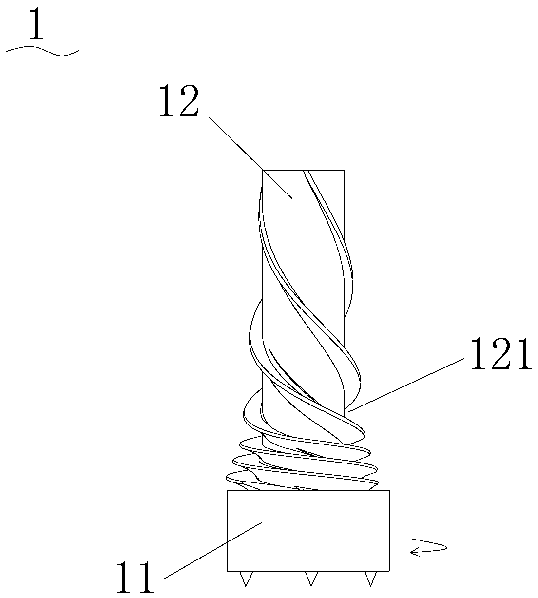
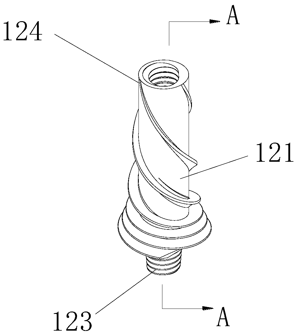
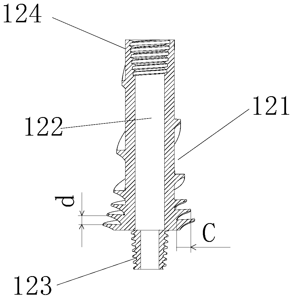
[0023] Such as Figure 1 to Figure 3 As shown, the anti-cover drill 1 of the present invention includes an anti-cover drill rod 12 and a drill bit 11, and the anti-cover drill rod tail end 124 is a drill rod connection end connected with other drill rods, and the anti-cover drill rod head end 123 is connected to the drill rod. The tail ends of the drill bits 11 are connected, that is, the head end 123 of the anti-cover drill pipe is the drill bit connection end, and the anti-cover drill pipe 12 is provided with a through hole 122 for leading the slag discharge medium. In order to prevent drilling, the outer surface of the anti-covering drill rod 12 is provided with a spiral groove 121 whose screw-in direction is opposite to the drilling rotation direction of the drill bit 11 .

[0024] Wherein, the method of judging the screwing direction of the spiral...


PUM


Abstract

The invention provides an anti-cover drill bit which can be anti-cover and does not affect the drilling depth of a drilling machine, and relates to the technical field of geological drilling tools. The anti-cover drill includes an anti-cover drill rod and a drill bit, the head end of the anti-cover drill rod is connected with the tail end of the drill bit, and a spiral groove with a screwing-in direction opposite to the rotation direction of a drill bit drilling hole is formed in the outer surface of the anti-cover drill rod. The anti-cover drill can ensure the drilling speed of the drilling hole.

Description

technical field [0001] The invention relates to the technical field of geological drilling tools, in particular to an anti-cover drill pipe and an anti-cover drill. Background technique [0002] During geological drilling, the drill cuttings produced by the cutting of the drill bit are discharged from the gap between the drill pipe and the hole wall, that is, the slag discharge medium is transported from the inside of the drill pipe to the drill hole, and the drill cuttings are discharged out of the drill hole while cooling the drill bit. . During the drilling process, the discharge resistance of the large-diameter drill cuttings generated by the cutting of the drill bit in the hole is much greater than that of the powdery cuttings, and its discharge speed is much lower than that of the powdery cuttings, so the drilling blockage is prone to occur. In addition, during the drilling process, due to the redistribution of various stresses in the borehole, the hole wall will shri...

Claims


Application Information

Patent Timeline
Patent Type & Authority Applications(China)
IPC IPC(8): E21B17/22
CPCE21B17/22
Inventor 杜海军刘海涛冯长春柳永红
Owner SICHUAN CHUANMEI HUARONG ENERGY CO LTD
Learn More