
Novel structure low-temperature pump

A new structure, cryogenic pump technology, applied in the direction of pumps, pump components, variable capacity pump components, etc., can solve the problems of inability to accurately monitor the displacement, the length of the cryopump connecting rod, the scale of the gasifier, etc., to improve the process performance, ensure accurate work, and facilitate maintenance.

Pending Publication Date: 2019-08-16
英嘉动力科技无锡有限公司
View PDF0 Cites 2 Cited by
  • Summary
  • Abstract
  • Description
  • Claims
  • Application Information

AI Technical Summary

Problems solved by technology

Existing reciprocating piston cryopumps have many defects: the connecting rod of the cryopump is long, and the two ends of the cryopump are connected to the piston through a threaded structure, which is easy to cause stagnation or even jamming during movement; the inside of the cryopump passes through the cone Or flat seal, the sealing surface is easy to leak; the driving end is directly connected to the cold end through ordinary metal parts, and the heat leakage is serious; the carburetor needs to pass the engine coolant during heat exchange, and after a period of use, there will be gas inside the carburetor. Scale cannot be cleaned and maintained; when the piston moves, the displacement cannot be accurately monitored, resulting in piston impact failure, etc.

Method used


Image

  • Novel structure low-temperature pump
  • Novel structure low-temperature pump
  • Novel structure low-temperature pump

Examples


Embodiment Construction

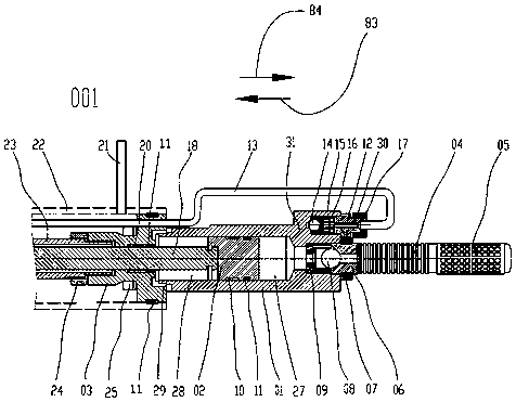
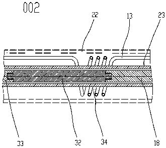
[0028] attached Figure 1-4 It is a specific embodiment of the present invention. The invention is a new structure cryopump, which includes a cold end area 001, a gaseous cooling area 002 and a hot end area 003. A gaseous cooling area 002 is provided between the cold end area 001 and the hot end area 003. The cold end area 001 includes Cold-end pump body 01, cold-end piston 02, cold-end connecting rod 18, etc. The cold-end pump body 01 is provided with a cold-end piston 02, and the end of the cold-end piston 02 is designed as a ring groove opening, and the cold-end connecting rod 18 The head is installed in the open ring groove of the piston, and the head of the cold end pump body 01 is equipped with a bellows 04, a filter 05, a ball seat 06, a liquid valve 09 and the first steel ball 08, and the first steel ball 08 is installed on the ball seat In the channel between the cone surface of 06 and the cone surface of liquid valve 09, a one-way valve body 15 and an air outlet joi...


PUM


Abstract

The invention belongs to the technical field of fuel supply for internal combustion engines, and in particular, relates to a novel structure low-temperature pump. The novel structure low-temperature pump comprises a cold end area, an air-state cooling area and a hot end area; the air-state cooling area is arranged between the cold end area and the hot end area; the cold end area comprises a cold end pump body and a vacuum insulation cover; a cold end piston is arranged in the cold end pump body; the end part of the cold end piston is designed in a ring groove opening form; the head part of a cold end connecting rod is mounted in a piston opening ring groove; the hot end area comprises a hot end piston; the hot end piston is mounted in a hot end pump body; a pressure relief device is arranged on the hot end piston; a displacement sensor is arranged on the hot end pump body; and a high-pressure air pipe is arranged in the air-state cooling area. The novel structure low-temperature pump has the following beneficial effects: liquefied natural gas in a low-temperature tank can be totally pumped out to improve the vehicle endurance; the structure is simple and effective; the reliabilityis improved; the machining manufacturability is excellent; and the batch production is convenient.

Description

technical field [0001] The invention belongs to the technical field of fuel supply for internal combustion engines, and in particular relates to a low-temperature pump with a new structure. Background technique [0002] In the current market, among internal combustion engine vehicles that use natural gas as fuel, natural gas is carried on the vehicle in two ways: compressed natural gas (CNG) and liquefied natural gas (LNG). Compressed natural gas (CNG) is gaseous natural gas at high pressure, usually one volume of compressed natural gas is converted to 200 standard volumes of natural gas. Liquefied natural gas (LNG) is natural gas in liquid form, usually one volume of LNG is converted into 600 standard volumes of natural gas. CNG vehicles have insufficient continuous driving ability and are suitable for small vehicles such as taxis. Compared with CNG vehicles, the continuous driving capacity of LNG vehicles is greatly increased, and medium and heavy trucks also have enough...

Claims


Application Information

Patent Timeline
Patent Type & Authority Applications(China)
IPC IPC(8): F04B37/08F04B39/00F04B39/10F02M21/02F02M21/06
CPCF04B37/08F04B39/00F04B39/10F02M21/0215F02M21/0221F02M21/0245F02M21/06Y02T10/30
Inventor 张建明姬广存
Owner 英嘉动力科技无锡有限公司
Learn More