
Displacement measuring device and method based on self-mixing holographic interference

A technology of displacement measurement and holographic interference, applied in the field of displacement measurement devices based on self-mixing holographic interference, can solve the problems of increased cost, bulky, complex optical path, etc., and achieves the effect of saving cost, reducing difficulty, and reducing space occupation

Active Publication Date: 2019-08-16
JIHUA LAB
View PDF9 Cites 0 Cited by
  • Summary
  • Abstract
  • Description
  • Claims
  • Application Information

AI Technical Summary

Problems solved by technology

This kind of interference system only needs one channel, simple structure, compact and easy to collimate, which solves the problems of traditional laser interferometry systems such as bulky, complex optical path and difficult collimation.
However, this self-mixing interferometry method has the problems of traditional interferometry, that is, the mirror to be tested is required, which increases the cost and increases the difficulty of installation and adjustment.

Method used


Image

  • Displacement measuring device and method based on self-mixing holographic interference
  • Displacement measuring device and method based on self-mixing holographic interference
  • Displacement measuring device and method based on self-mixing holographic interference

Examples


Embodiment Construction

[0023] Preferred embodiments of the present invention will be described in detail below with reference to the accompanying drawings, so as to better understand the purpose, features and advantages of the present invention. It should be understood that the embodiments shown in the drawings are not intended to limit the scope of the present invention, but only to illustrate the essence of the technical solutions of the present invention.

[0024] In the following description, for the purposes of explaining the various disclosed embodiments, certain specific details are set forth in order to provide a thorough understanding of the various disclosed embodiments. One skilled in the relevant art will recognize, however, that an embodiment may be practiced without one or more of these specific details. In other instances, well-known devices, structures and techniques associated with the present application may not have been shown or described in detail in order to avoid unnecessarily...


PUM


Abstract

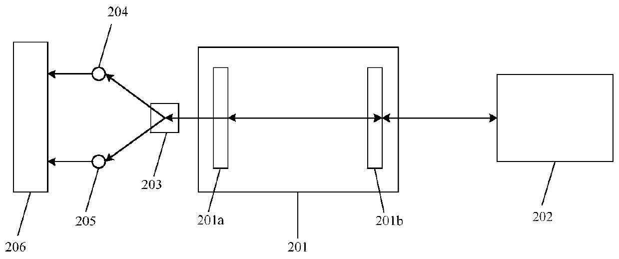
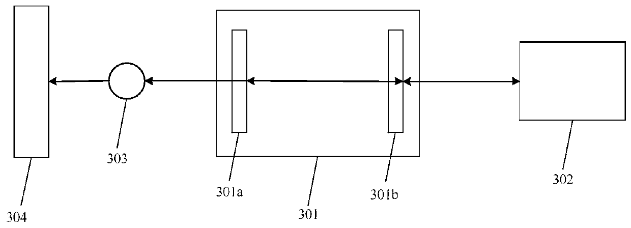
The invention discloses a displacement measuring device and method based on self-mixing holographic interference. The displacement measuring device comprises a laser, a signal detector and a signal processing circuit, wherein the laser is provided with a laser resonant cavity, and a first endoscope and a second endoscope are arranged at the two ends of the laser resonant cavity; a measuring lightbeam emitted by the laser carries the displacement information of a tested object, is returned to the laser resonant cavity through the first endoscope, and is subjected to self-mixing holographic interference with a reference light beam in the laser resonant cavity to form interference light; the interference light is output through the second endoscope and is received through the signal detector, wherein the signal detector is used for converting the received optical signal into an electric signal; and the signal processing circuit is used for processing the electric signal into a displacement signal which can be read and analyzed by an upper computer. According to the displacement measuring device, the difficulty of light path adjustment is greatly reduced; in addition, the cost is saved; and meanwhile, the space occupation can be reduced.

Description

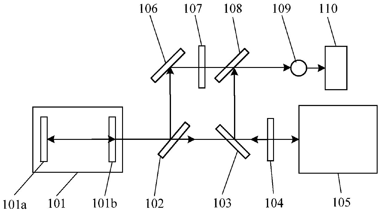
technical field [0001] The invention relates to the field of displacement measuring devices, in particular to a displacement measuring device and method based on self-mixing holographic interference. Background technique [0002] With the advancement and development of science and technology, people's demand for displacement measurement is getting higher and higher. For the measurement of micron or even nanometer level, laser interferometry is widely used for measurement. The typical product is Michelson laser interferometer. The object has relatively high requirements, for example, there must be a reflector on the measured object, and there are high requirements for the surface accuracy and surface finish of the reflector. Based on this, people have proposed a measurement method using holographic interference, which greatly reduces the requirements for the measured object. [0003] Traditional holographic interferometry devices such as figure 1 As shown, the holographic ...

Claims


Application Information

Patent Timeline
IPC IPC(8): G01B9/02G01B11/30
CPCG01B9/02029G01B11/303
Inventor 杨晓峰郝凌凌张志平
Owner JIHUA LAB
Learn More