Microwave sensor for synchronously measuring dielectric constant and magnetic conductivity of magnetic medium material

A microwave sensor and dielectric constant technology, applied in the microwave field, can solve the problems of single sensor function, inability to measure the dielectric constant and magnetic permeability at the same time, without considering the influence of external factors, etc., and achieve the effect of eliminating the influence of environmental factors

Active Publication Date: 2019-08-16
HANGZHOU DIANZI UNIV
View PDF8 Cites 11 Cited by
  • Summary
  • Abstract
  • Description
  • Claims
  • Application Information

AI Technical Summary

Problems solved by technology

Therefore, the measurement of the permittivity and permeability of the magnetic medium material is independent of each other, and the sensor has a single function, which can only be aimed at the measurement of a certain parameter, and cannot measure the permittivity and permeability at the sam

Method used


Image

  • Microwave sensor for synchronously measuring dielectric constant and magnetic conductivity of magnetic medium material
  • Microwave sensor for synchronously measuring dielectric constant and magnetic conductivity of magnetic medium material
  • Microwave sensor for synchronously measuring dielectric constant and magnetic conductivity of magnetic medium material

Examples


Embodiment Construction

[0030] The present invention will be described in further detail below with specific embodiments in conjunction with the accompanying drawings.

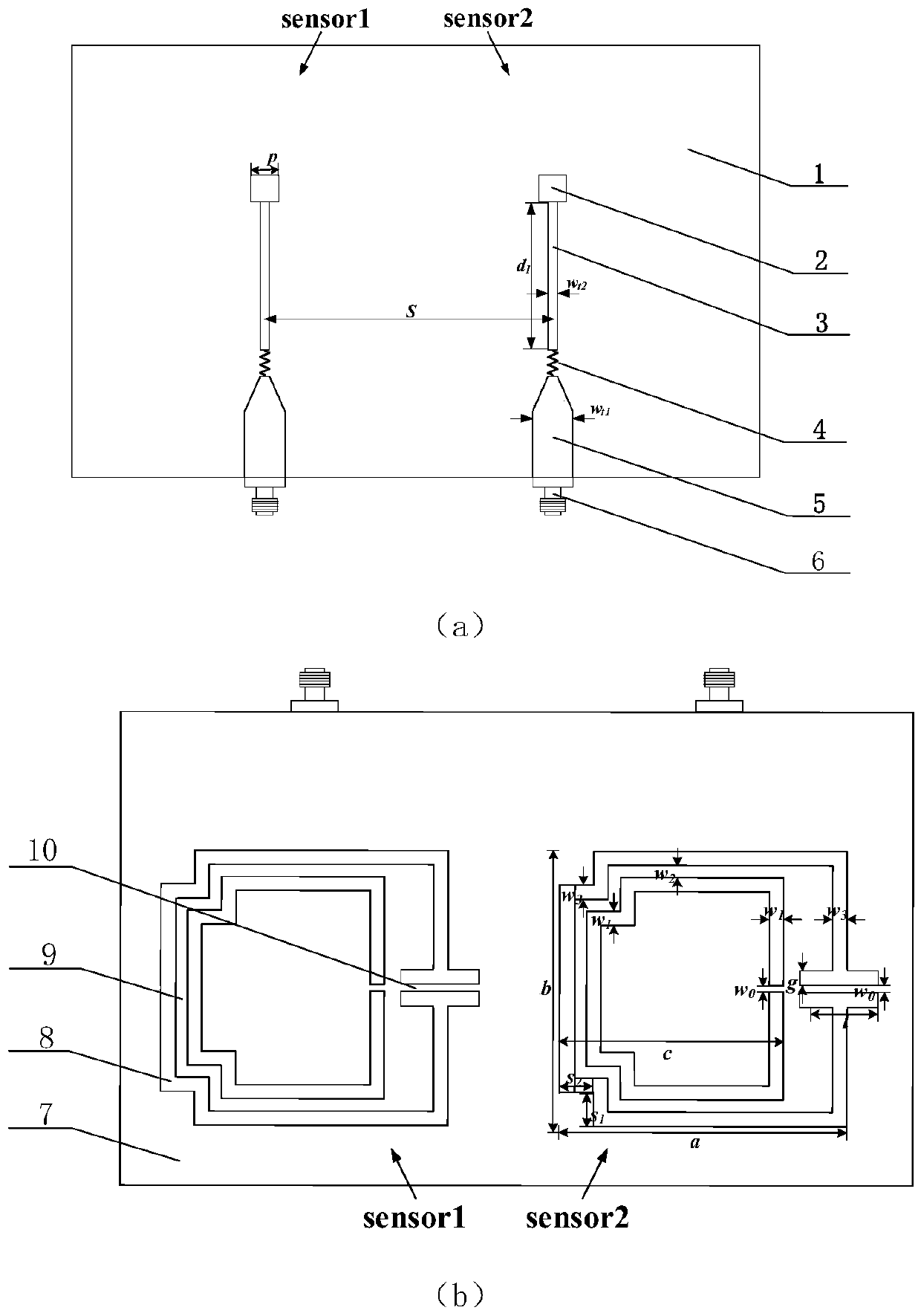
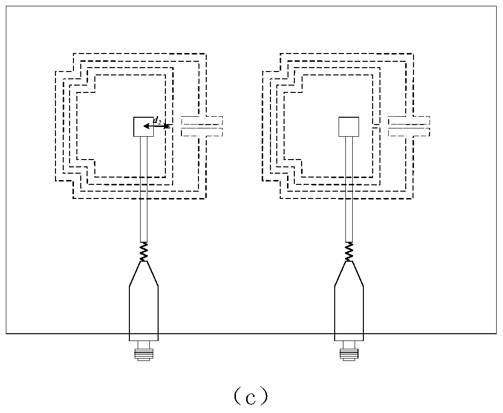
[0031] Such as figure 1 Shown is the structure schematic diagram of the present invention, and the differential sensor of the present invention is made up of two sensors, and each sensor comprises the CSRR groove ring 8 that top layer microstrip line, middle layer PCB board 1, bottom metal sheet 7 are etched; The strip line includes microstrip line Ⅰ3 and microstrip line Ⅱ5, and the microstrip line Ⅰ3 and microstrip line Ⅱ5 are welded through a 50Ω resistor 3, and the metal patch 2 is connected to the other end of the microstrip line Ⅰ3, and the other end of the microstrip line Ⅰ3 One end extends the feed long leg for connecting to the SMA connector 6; the metal patch 2 is coupled to the underlying metal sheet 7;

[0032] Each grooved metal CSRR structure is composed of inner and outer groove rings, and the openings of the two groov...


PUM


Abstract

The invention discloses a microwave sensor for synchronously measuring a dielectric constant and magnetic conductivity of a magnetic medium material. The microwave sensor comprises two microstrip linestructures, a medium layer, a metal sheet and two slotted metal CSRR (complementary split-ring resonator) structures from a top layer to a bottom layer. Each slotted metal CSRR structure is composedof an inner slot ring and an outer slot ring, wherein each of the inner slot ring and the outer slot ring is provided with an opening, and facing directions of the openings are identical; two oppositeright angles of the opening of the inner slot ring and two opposite right angles of the opening of the outer slot ring are all folded inwards in an alignment mode, and the opening of the outer slot ring extends towards the inside and outside of the outer slot ring to form channels; the part between the channels of the opening of the outer slot ring is a region with maximum magnetic field intensity, and the region is used to contain a to-be-detected sample for measuring the magnetic conductivity of the sample; and the part between the channels, where the two inwards-folded right angles of theinner slot ring and the two inwards-folded right angles of the outer slot ring are connected, is a region with maximum electric field intensity, and the region is used to contain the to-be-detected sample for measuring the dielectric constant of the sample. According to the microwave sensor, the form of a differential structure is adopted, differential measurement can be performed on the dielectric constant and the magnetic conductivity, and the influence of environment factors is eliminated by the adoption of a relative measurement mode.

Description

technical field [0001] The invention belongs to the field of microwave technology, and relates to a microstrip line excitation sensor, in particular to a differential microwave sensor for synchronously measuring the permittivity and permeability of magnetic medium materials based on single-ended microstrip line magnetic coupling. Background technique [0002] With the rapid development of microwave technology in many industries (such as military, medical, food, chemical and meteorology, etc.), various types of radio frequency microwave devices have been gradually developed and applied. The electromagnetic properties of magnetic media materials greatly affect the performance parameters of equipment devices, so the research on the electromagnetic properties of magnetic media materials is very important. [0003] The electromagnetic properties of magnetic media materials are characterized by three parameters: permittivity ε, magnetic permeability μ, and electrical conductivity ...

Claims


Application Information

Patent Timeline
IPC IPC(8): G01R27/26G01R33/12
CPCG01R27/2623G01R33/1223
Inventor 赵文生甘宏祎胡月王晶王高峰
Owner HANGZHOU DIANZI UNIV
Why Eureka
Try Eureka