Silicon wafer de-gluing machine and control method thereof

A technology for degumming machines and silicon wafers, which is applied in the fields of chemical instruments and methods, semiconductor/solid-state device manufacturing, water/sludge/sewage treatment, etc. It can solve the problems of poor spraying effect and low utilization rate of spraying water, and achieve The effects of saving water, improving the surface quality of silicon wafers, and reducing production costs

Pending Publication Date: 2019-08-16
INNER MONGOLIA ZHONGHUAN SOLAR MATERIAL
View PDF0 Cites 2 Cited by
  • Summary
  • Abstract
  • Description
  • Claims
  • Application Information

AI Technical Summary

Problems solved by technology

[0004] The problem to be solved by the present invention is to provide a silicon chip degumming machine and its control method, especially suitable for the recovery device and its control of the spray liquid in the spray tank process, which solves the problem of the spray effect in the spray process in the prior art. Poor, can not meet the existing production technology requirements, the technical problem of low utilization rate of spray water, the purpose is to improve the surface quality of silicon wafers, reduce production costs and improve product quality

Method used


Image

  • Silicon wafer de-gluing machine and control method thereof
  • Silicon wafer de-gluing machine and control method thereof
  • Silicon wafer de-gluing machine and control method thereof

Examples


Embodiment 1

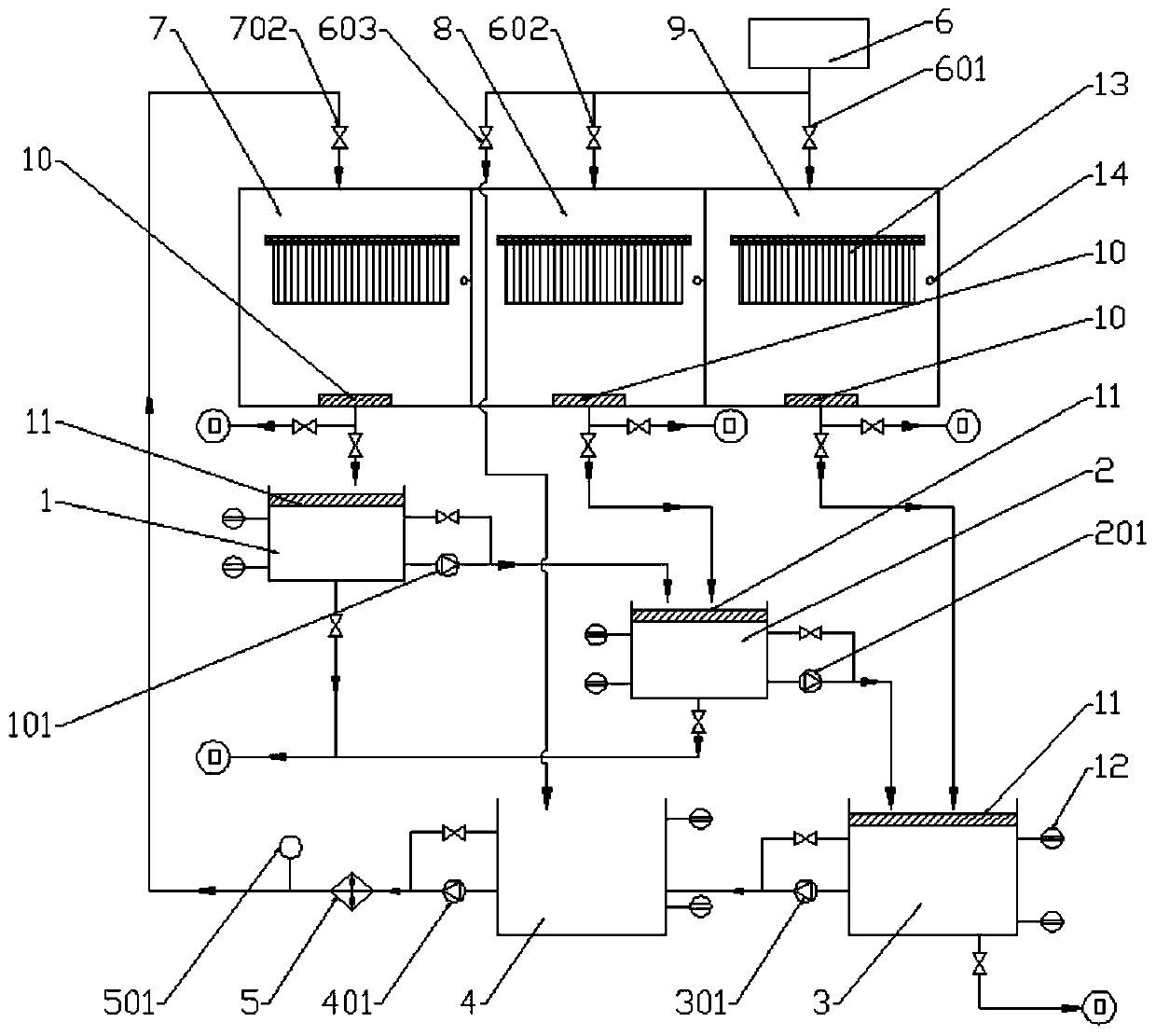
[0053] A silicon wafer degumming machine, such as figure 1 As shown, it includes the first groove 7, the second groove 8 and the third groove 9 used for spraying silicon wafers, and the first groove 7, the second groove 8 and the third groove 9 are arranged independently in sequence, and also includes the primary filter box 1, The secondary filter box 2, the tertiary filter box 3, the water storage tank 4, the heater 5, the pure water source 6 and the controller.

[0054]Wherein, the primary filter box 1 communicates with the outlet of a tank 7 through a water pipe, and is used for recovering the waste water discharged from the tank 7 . The input port of the secondary filter box 2 communicates with the output port of the primary filter box 1 and the drain of the second tank 8 through water pipes, and the secondary filter box 2 is used to filter the water discharged from the primary filter box 1 and recover the water from the secondary filter box 1. Wastewater discharged from ...

Embodiment 2

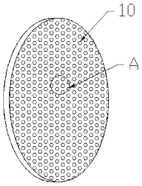
[0078] Such as Figure 5 As shown, compared with Embodiment 1, the biggest difference of this embodiment is that the waste water sprayed from the second tank 8 is filtered by the first filter screen 10 and discharged into the third stage together with the waste water sprayed from the third tank 9 Recycling and filtering are carried out in the filter box 3 , and then enter the water storage tank 4 after being filtered by the second filter screen 11 arranged in the three-stage filter screen 3 . That is to say, the secondary filter box 2 only filters the water filtered from the primary filter box 1, and the water filtered by the secondary filter box 2 enters the tertiary filter box 3 together with the waste water discharged from the second tank 8 and the third tank 9 filter in. The setting of this structure can also realize the recycling of spray water, with a high utilization rate, and realize the purpose of saving water to the greatest extent. 7 Spray use requirements, saving...


PUM


Abstract

The invention provides a silicon wafer de-gluing machine which comprises a primary filter box which is communicated with a first tank and used for recovering waste water discharged from the tank; a secondary filter box which is communicated with the primary filter box and used for filtering the water discharged from the primary filter box; a tertiary filter box which is communicated with the secondary filter tank and a third tank and used for filtering the water discharged from the secondary filter box and recovering the waste water discharged from the third tank; a water storage tank which iscommunicated with the tertiary filter box and the first tank and used for storing water discharged from the tertiary filter tertiary and supplying spray water to the first tank; a heater which is isarranged between the water storage tank and the first tank and used for heating water discharged from the water storage tank; a pure water source which replenishes the water storage tank with the spray water; and a controller which detects existence of silicon wafers sprayed in the spray tank by position sensors arranged in the first tank, the second tank and the third tank and discharges the spray water from the water storage tank and/or the pure water source. The invention also provides a control method of the silicon wafer de-gluing machine. The surface quality of the silicon wafer can be improved, the spray water can be recycled, the production cost can be reduced and the product quality can be improved.

Description

technical field [0001] The invention belongs to the technical field of degumming of solar-grade monocrystalline silicon wafers, and in particular relates to a silicon wafer degumming machine and a control method thereof. Background technique [0002] In the production process of solar silicon wafers, the surface quality of silicon wafers is high, and the degumming process is an auxiliary process of wire cutting and cleaning. The degumming process directly affects the surface quality of subsequent silicon wafer cleaning. In the existing degumming machine, the silicon chip unloaded from the cutting machine enters the spray tank together with the resin plate for spray pre-cleaning, the purpose is to remove the silicon powder and cutting fluid adhered to the surface of the silicon chip, and at the same time clean the resin plate. The glue is softened, and the cutting fluid is the coolant used when cutting the silicon rod with the diamond cutting wire, and the pure water content ...

Claims


Application Information

Patent Timeline
Patent Type & Authority Applications(China)
IPC IPC(8): H01L21/67C02F1/00
CPCC02F1/001H01L21/67051
Inventor 张红霞梁宇飞白建军郭志荣
Owner INNER MONGOLIA ZHONGHUAN SOLAR MATERIAL
Why Eureka
Try Eureka