
Unit cell for fuel cell

A unit battery and fuel cell technology, applied in the direction of fuel cells, power system fuel cells, battery electrodes, etc., can solve the problem of changing the additional cost of the mold structure, and achieve the effect of a stable contact state

Pending Publication Date: 2019-08-16
HYUNDAI MOTOR CO LTD +1
View PDF7 Cites 0 Cited by
  • Summary
  • Abstract
  • Description
  • Claims
  • Application Information

AI Technical Summary

Problems solved by technology

Therefore, the formed porous body has the following problems: many costs are required when installing the mold, and in the case where shape change is required for design purposes while optimizing the formed porous body, additional cost is required for changing the structure of the mold

Method used


Image

  • Unit cell for fuel cell
  • Unit cell for fuel cell
  • Unit cell for fuel cell

Examples


Embodiment Construction

[0049] Hereinafter, some embodiments of the present disclosure will be described in detail with reference to the accompanying drawings. In the following description, the same reference numerals will be assigned to the same elements although they are shown in different drawings. Also, in the following description of the embodiments of the present disclosure, detailed descriptions of well-known features or functions will be excluded in order to avoid unnecessarily obscuring the gist of the present disclosure.

[0050] In the following description of elements according to embodiments of the present disclosure, words “first”, “second”, “A”, “B”, “(a)”, and “(b)” may be used. These words are only used to distinguish a related element from other elements, and the nature, order or sequence of the related element is not limited to these words. Also, unless otherwise defined, all terms (including technical or scientific terms) used herein have the same meaning as commonly understood b...


PUM


Abstract

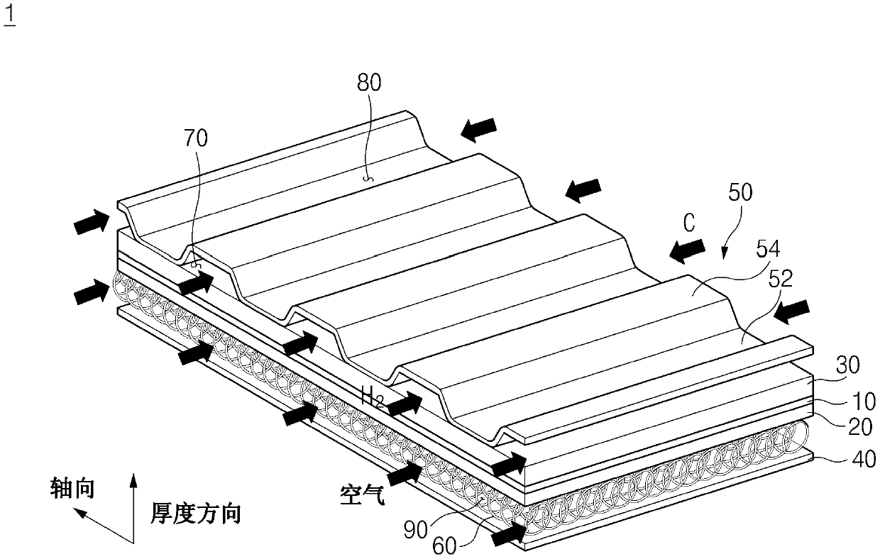
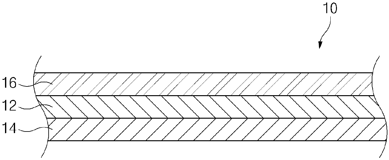
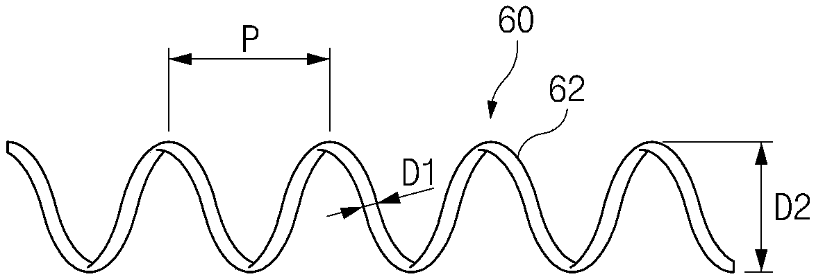
A unit cell for a fuel cell includes a membrane-electrode-assembly (MEA), a gas diffusion layer disposed on one surface of the MEA, a separator plate disposed to be spaced from the gas diffusion layer, and at least one coil spring interposed between the gas diffusion layer and the separator plate to elastically support the gas diffusion layer and the separator plate while electrically connecting the gas diffusion layer with the separator plate and providing a reactant gas passage to transfer reactant gas.

Description

[0001] Cross References to Related Applications [0002] This application claims priority from Korean Patent Application No. 10-2018-0016449 filed on February 9, 2018, which is hereby incorporated herein by reference. technical field [0003] The present disclosure relates to a unit cell for a fuel cell. Background technique [0004] A fuel cell stack is a device that generates electricity, which is a main power source of a fuel cell vehicle, through a redox reaction of hydrogen and oxygen. [0005] Generally, a fuel cell stack is formed by stacking a plurality of unit cells including a membrane electrode assembly (MEA) and separators disposed on both sides of the MEA. [0006] The MEA includes a polymer electrolyte membrane, an anode disposed on one surface of the polymer electrolyte membrane, and a cathode disposed on the opposite surface of the polymer electrolyte membrane. The separator includes hydrogen channels for supplying hydrogen to the anode, air channels for su...

Claims


Application Information

Patent Timeline
Patent Type & Authority Applications(China)
IPC IPC(8): H01M8/1004H01M8/1006H01M8/1007H01M8/0258
CPCH01M8/1004H01M8/1006H01M8/1007H01M8/0258H01M2250/20H01M8/0265H01M8/0297Y02E60/50H01M8/0254H01M8/04089H01M4/8807
Inventor 金正翊
Owner HYUNDAI MOTOR CO LTD
Learn More