
Control method, device and system for additive manufacturing and storage medium

An additive manufacturing and control method technology, applied in the field of mechanical processing, can solve the problems of difficult to meet the precise control of laser molten pool solidification structure, difficult to achieve micro-scale precise control and customized distribution of mechanical properties, etc., to achieve a large degree of control freedom. Effect

Active Publication Date: 2019-08-20
SOUTH UNIVERSITY OF SCIENCE AND TECHNOLOGY OF CHINA
View PDF6 Cites 2 Cited by
  • Summary
  • Abstract
  • Description
  • Claims
  • Application Information

AI Technical Summary

Problems solved by technology

[0003] In the actual laser powder feeding additive manufacturing process, affected by factors such as component shape changes, heat accumulation in the cladding area, and thermal cycles, the dependence of the molten pool solidification structure on process parameters is uncertain, resulting in the microstructure of laser additive manufacturing components. And its mechanical properties are difficult to achieve precise micro-scale regulation and macro-customized distribution
At present, by adding various auxiliary control methods such as vibration, constant magnetic field, electric field, and coupled electric-magnetic field in the laser additive manufacturing process, the solidification structure of the laser molten pool can be regulated to a certain extent, but the existing auxiliary methods are still It is difficult to meet the precise regulation of the microscale of the solidification structure of the laser molten pool
[0004] Therefore, using the existing laser additive manufacturing process and auxiliary control methods, there are still huge challenges in the local precise regulation of the molten pool solidification structure and the macroscopic customized distribution.

Method used


Image

  • Control method, device and system for additive manufacturing and storage medium
  • Control method, device and system for additive manufacturing and storage medium
  • Control method, device and system for additive manufacturing and storage medium

Examples


Embodiment 1

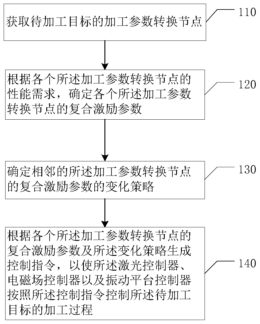
[0027] figure 1 It is a flow chart of a control method for additive manufacturing provided by Embodiment 1 of the present invention. This embodiment is applicable to the control of additive manufacturing technology. The method can be executed by a control device for additive manufacturing, specifically including Follow the steps below:

[0028] Step 110, acquiring the processing parameter transformation node of the object to be processed.

[0029] Wherein, the processing parameter conversion node refers to the node where the processing parameters of the object to be processed change. The number of processing parameter conversion nodes will vary with the target to be processed and its processing technology. It can be one, two, three or even more, mainly depending on the complexity of the processing technology.

[0030] Optionally, the processing parameter conversion node of the object to be processed can be determined through the processing technology and the processing route...

Embodiment 2

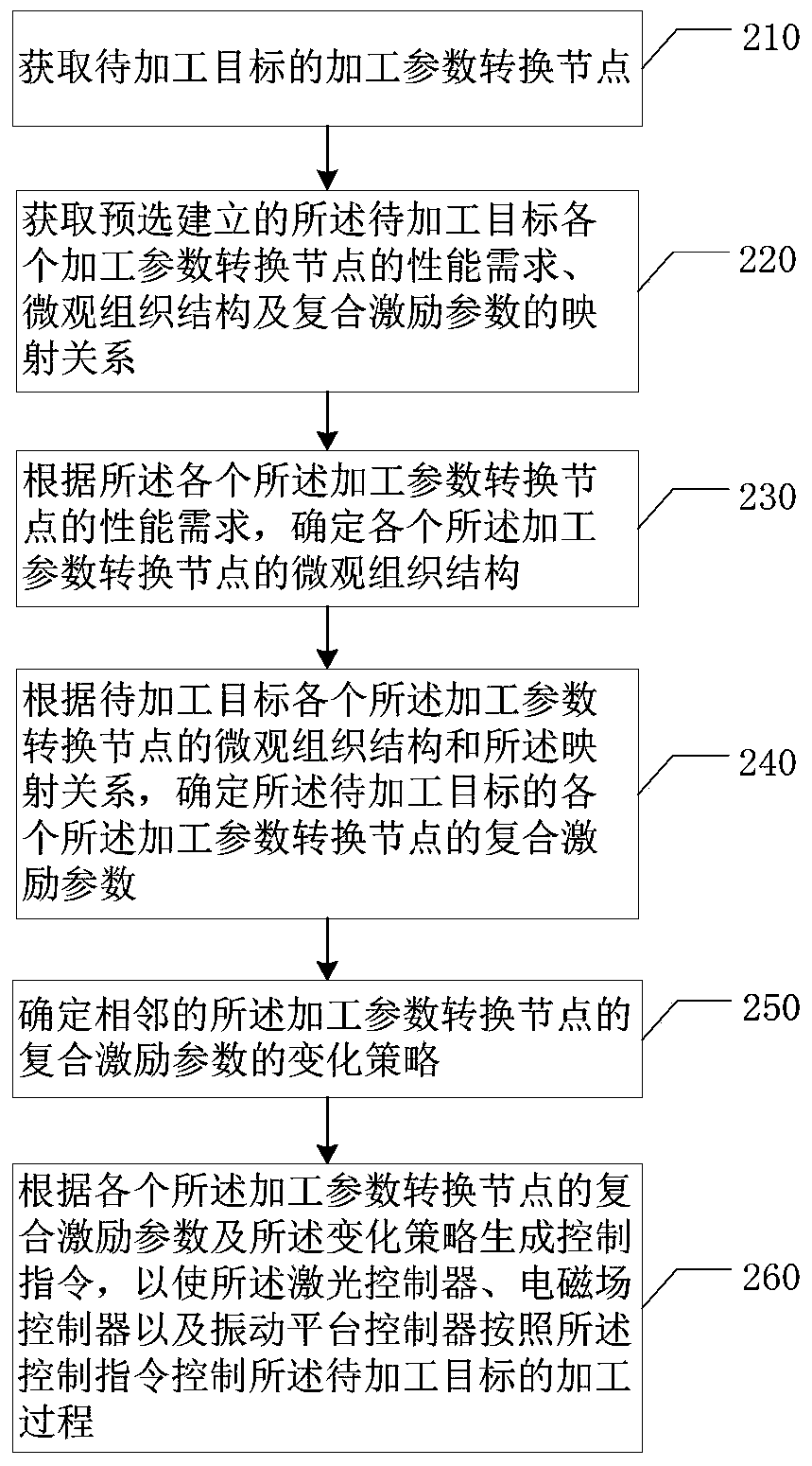
[0055] figure 2 It is a flow chart of a control method for additive manufacturing in Embodiment 2 of the present invention. The technical solution of this embodiment is supplemented on the basis of the above technical solution. Optionally, such as figure 2 As shown, the method for pushing preferential information provided by the embodiment of the present invention includes:

[0056] Step 210, acquiring the processing parameter transformation node of the object to be processed.

[0057] Step 220, obtaining the pre-selected and established mapping relationship between performance requirements, microstructure and compound excitation parameters of each processing parameter conversion node of the target to be processed.

[0058] Optionally, the above mapping relationship can be formulated by analyzing the material of the target to be processed, including the macroscopic and microscopic properties of the material, and through coupling analysis of the influence of each excitation ...

Embodiment 3

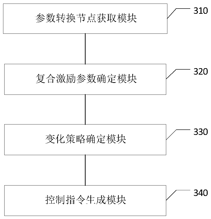
[0068] image 3 It is a schematic structural diagram of a control device for additive manufacturing in Embodiment 3 of the present invention, such as image 3 As shown, the control device for additive manufacturing includes: a parameter conversion node acquisition module 310 , a compound excitation parameter determination module 320 , a change strategy determination module 330 and a control command generation module 340 .

[0069] The parameter conversion node acquisition module 310 is used to obtain the processing parameter conversion node of the target to be processed; the composite excitation parameter determination module 320 is used to determine the composite of each processing parameter conversion node according to the performance requirements of each of the processing parameter conversion nodes. Excitation parameters, wherein the composite excitation parameters include laser excitation parameters, electromagnetic field excitation parameters and vibration platform excita...


PUM


Abstract

The invention discloses a control method, device and system for additive manufacturing and a storage medium. The control method for additive manufacturing comprises the steps that machining parameterswitching nodes of a to-be-machined target are obtained; compound excitation parameters of the machining parameter switching nodes are determined according to the performance requirements of the machining parameter switching nodes, wherein the compound excitation parameters include the laser excitation parameter, the electromagnetic field excitation parameter and the vibrating platform excitationparameter; a change strategy of the compound excitation parameters of every two adjacent machining parameter switching nodes is determined; and a control command is generated according to the compoundexcitation parameters of the machining parameter switching nodes and the change strategies, so that a laser controller, an electromagnetic field controller and a vibrating platform controller are made to control the machining process of the to-be-machined target according to the control command. By adoption of the technical scheme of the embodiment, accurate control and regulation of microstructures during additive manufacturing are achieved, and the degree of freedom of regulation and control is large.

Description

technical field [0001] Embodiments of the present invention relate to mechanical processing technology, and in particular to a control method, device, system and storage medium for additive manufacturing. Background technique [0002] As an additive manufacturing technology, laser powder feeding cladding technology has been widely used in the field of metal parts manufacturing. Combining laser powder feeding cladding technology with industrial manipulators, high-power lasers are used to melt and deposit coaxially conveyed metal powder materials, which are overlapped and clad one by one to form layers, and stacked layer by layer to form three-dimensional components. With the increasing demand for high-performance gradient functional components in aerospace, nuclear power, marine and medical fields, the use of laser powder-fed cladding technology to manufacture gradient tissue materials has great development space and application value. [0003] In the actual laser powder fee...

Claims


Application Information

Patent Timeline
Patent Type & Authority Applications(China)
IPC IPC(8): B22F3/105B33Y50/02
CPCB33Y50/02B22F10/00B22F12/30B22F12/50B22F10/25B22F10/36B22F12/22Y02P10/25
Inventor 叶国威刘朝阳朱强李欣
Owner SOUTH UNIVERSITY OF SCIENCE AND TECHNOLOGY OF CHINA
Learn More