
A blanking device for a laser pipe cutting machine

A pipe cutting machine and blanking technology, which is applied to laser welding equipment, tubular objects, manufacturing tools, etc., can solve the problems of pipe damage, affecting the work safety of staff, and messy working environment, so as to ensure cleanliness and avoid damage.

Active Publication Date: 2020-04-17
JINAN BODOR LASER CO LTD
View PDF10 Cites 1 Cited by
  • Summary
  • Abstract
  • Description
  • Claims
  • Application Information

AI Technical Summary

Problems solved by technology

[0004] However, for the scraps left inside the pipe when processing the side wall and the waste residue generated during pipe cutting, the existing laser pipe cutting machine is not equipped with a cutting mechanism, and the scraps and residues falling on the ground often lead to messy working environment. Affect the work safety of the staff. During the transportation of the pipeline, the untreated scrap waste will also cause damage to the pipeline.

Method used


Image

  • A blanking device for a laser pipe cutting machine
  • A blanking device for a laser pipe cutting machine
  • A blanking device for a laser pipe cutting machine

Examples


Embodiment Construction

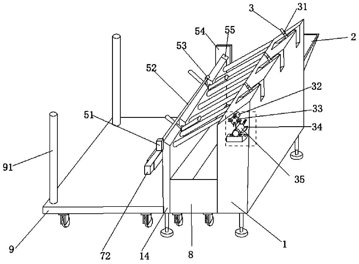
[0028] The present invention will be further described below in conjunction with the accompanying drawings and embodiments.

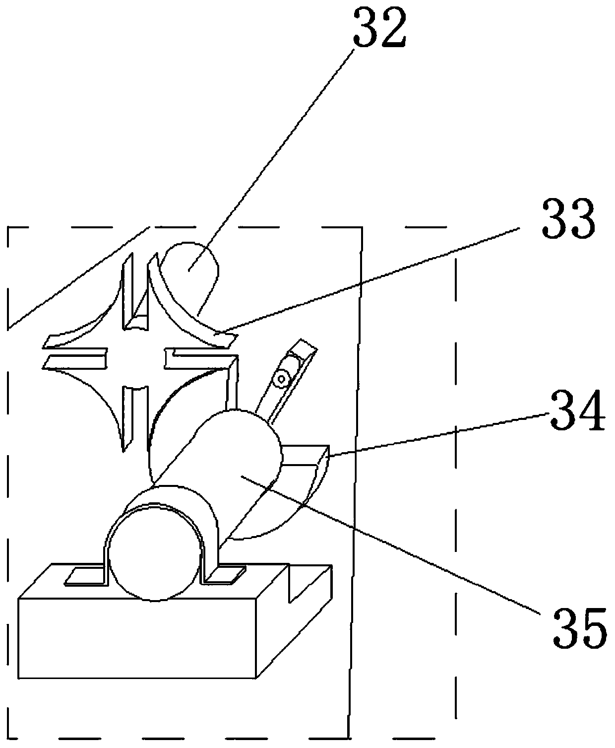
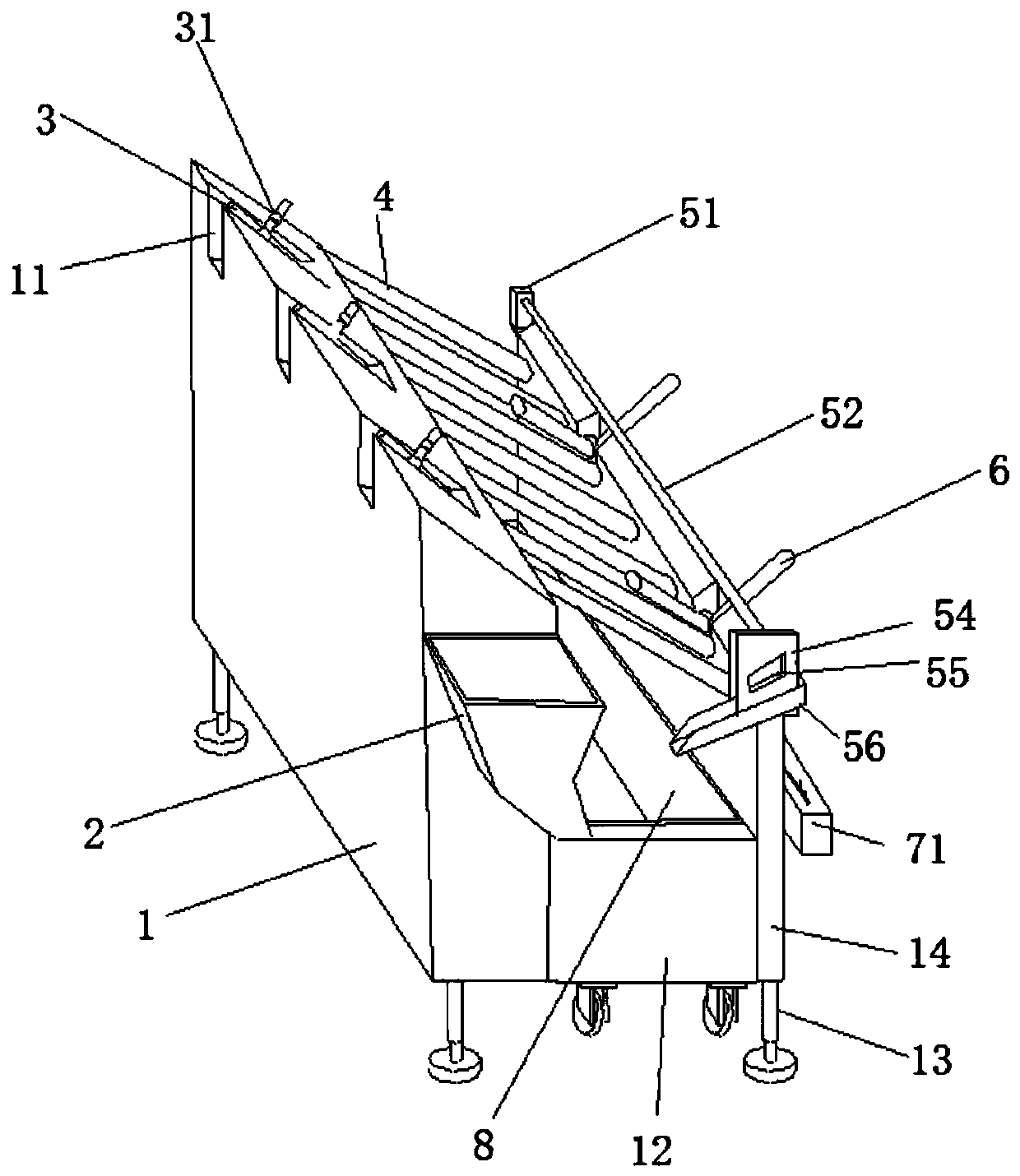
[0029] Please refer to figure 1 , figure 2 , image 3 , Figure 4 as well as Figure 5 ,in figure 1 A schematic structural diagram of a preferred embodiment of the blanking device of the laser pipe cutting machine provided by the present invention; figure 2 for figure 1 The enlarged schematic diagram of the structure at the dotted box shown; image 3 for figure 1 The schematic diagram of the other side of the unloading device of the laser pipe cutting machine shown; Figure 4 for figure 1 A schematic cross-sectional view of the telescopic rod shown; Figure 5 for Figure 4 Schematic diagram of the enlarged structure of the structure shown in the dotted box.

[0030] combined reference figure 1 and image 3As shown, a blanking device of a laser pipe cutting machine includes a support platform 1, a side wall at one end of the support platf...


PUM


Abstract

The invention provides an unloading device of a laser pipe cutting machine. The device comprises a slag receiving hopper, a support table, a support plate, a connecting rod, a waste slag car, a collecting car, an extension rod, a pipe penetrating mechanism and a first rotating frame; the slag receiving hopper is arranged on the support table; the first rotating frame is arranged on the support plate; the connecting rod is arranged between the support table and the support plate; the waste slag car is placed between the support table and the support plate; the collecting car is placed on one side of the support plate; the extension rod is fixed on the support plate, and is provided with the pipe penetrating mechanism; the slag receiving hopper receives waste slag splashed in the machining process; and through rolling of pipes and extension of the pipe penetrating mechanism into the pipes, the waste slag and leftovers in the pipes are pulled out to fall into the waste slag car, so that the working environment of workers is safe and tidy, and the pipes have no waste slag and leftover after unloading to prevent damage.

Description

technical field [0001] The invention relates to the field of laser cutting, in particular to a cutting device for a laser pipe cutting machine. Background technique [0002] In the process of laser pipe cutting, the laser pipe cutting machine is sometimes required to process side through holes, fixing holes, etc. on the side wall of the pipe, and when processing the side wall of the pipe, the waste generated by processing tends to stay inside the pipe. [0003] The unloading device of the existing laser pipe cutting machine generally includes a lifting and receiving device, a material receiving and retracting device and a chain conveying device. The lifting and receiving device is used to catch the material and can drive the material to lift; The material receiving and retracting device is used to drive the lifting material receiving device to move in translation, and the material on the lifting material receiving device is transported to the chain conveying device; the chai...

Claims


Application Information

Patent Timeline
Patent Type & Authority Patents(China)
IPC IPC(8): B23K26/38B23K26/16B23K26/70B23K101/06
CPCB23K26/16B23K26/38B23K26/702B23K2101/06
Inventor 杨绪广于飞路世强韩小鹏
Owner JINAN BODOR LASER CO LTD
Learn More