Flowing-through type water sterilizing device and water purifying facility

A water sterilization and over-flow technology, which is applied in water/sewage treatment equipment, water/sewage treatment, light water/sewage treatment, etc. It can solve the problems of unstable sterilization rate, large randomness, and poor heat dissipation capacity of light source. , to achieve the effect of improving light utilization

Pending Publication Date: 2019-08-20
深圳市侑为技术有限公司
View PDF6 Cites 7 Cited by
  • Summary
  • Abstract
  • Description
  • Claims
  • Application Information

AI Technical Summary

Problems solved by technology

The ultraviolet dosage received by microorganisms in the water body is unstable, the randomness is large, and the sterilization rate is unstable
[0006] 2. Low utilization rate of deep ultraviolet light
The UVC-LED light source part of the existing disclosed sterilizer only relies on th

Method used


Image

  • Flowing-through type water sterilizing device and water purifying facility
  • Flowing-through type water sterilizing device and water purifying facility
  • Flowing-through type water sterilizing device and water purifying facility

Examples


Embodiment 1

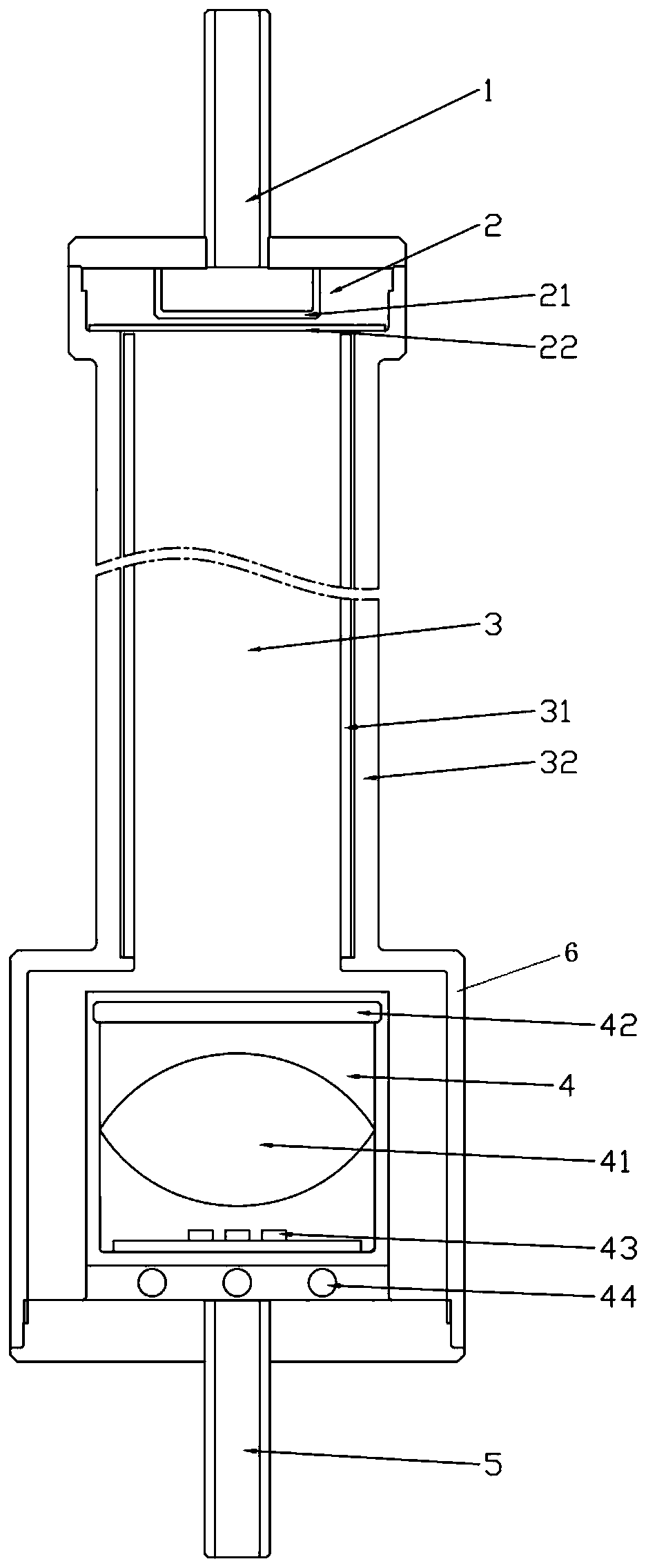
[0050] Such as figure 1 As shown, a flow-through water sterilization device includes a water inlet 1, a rectification module 2, a sterilization chamber 3, a UVC-LED light source assembly 4, a light source tube 6 and a water outlet 5, and the water inlet 1 and the rectification module 2 connection, the rectifier module 2 is connected to the inlet end of the sterilization chamber 3, the UVC-LED light source assembly 4 is located in the light source tube 6 and is located at the outlet end of the sterilization chamber 3, and the connection with the sterilization chamber 3 The outlet end is connected to the light source tube 6; the light source tube 6 is connected to the water outlet 5; the sterilizing cavity 3 includes a reflective sleeve 31 and a cavity shell 32, and the reflective sleeve and the cavity shell 32 are provided with The gap is filled with air, and the upper and lower ends of the gap are waterproofed with sealing rings.

[0051] The UVC-LED light source assembly 4 i...

Embodiment 2

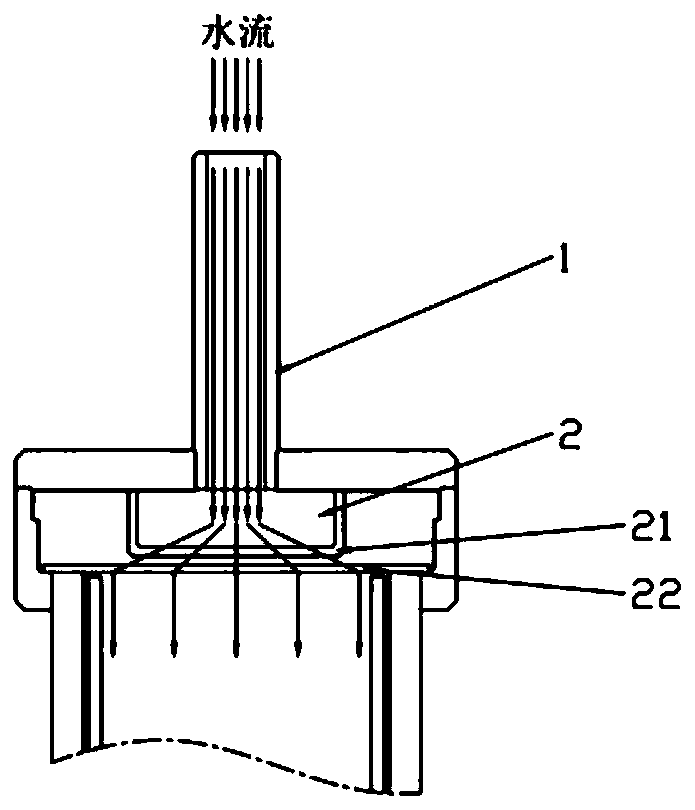
[0057] Such as figure 1 and figure 2 As shown, on the basis of Embodiment 1, the rectifying member includes a first rectifying member 21 and a second rectifying member 22, the second rectifying member 22 is located below the first rectifying member 21, and the first rectifying member 21 is a circular structure in the shape of a groove, the first rectification member 21 is coaxial with the water inlet 1, and several holes are opened on the first rectification member 21 to guide the flow. The first rectifying member 21 blocks and buffers the high-speed water flow at the inlet, and at the same time guides the water flow to spread and enter the second rectifying member 22 . The second rectifying member 22 is a circular perforated plate, the middle opening of the perforated plate is sparse, and the edge openings are dense. The water flow velocity at each position of the section remains consistent; it is beneficial to increase the sterilization time and sterilization stability. ...

Embodiment 3

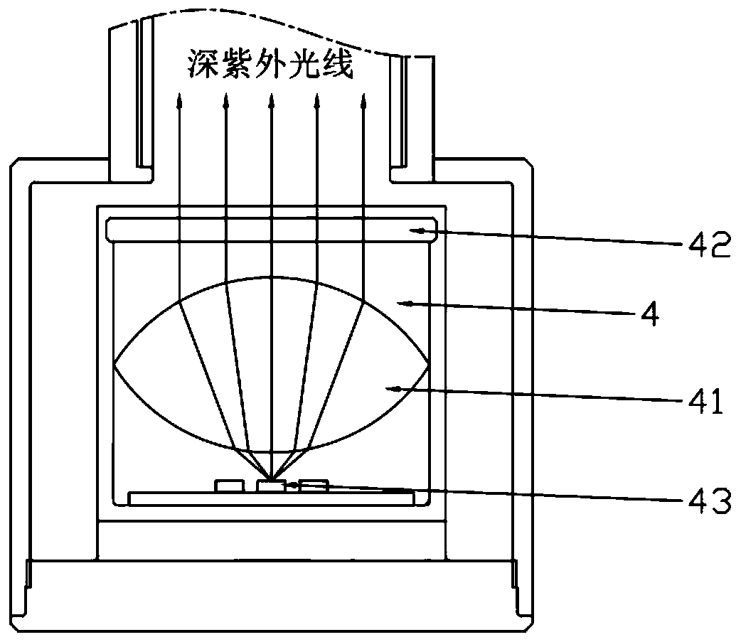
[0059] Such as figure 1 and image 3 As shown, on the basis of Embodiment 2, the optical lens includes a first optical lens 41 and a second optical lens 42, the second optical lens 42 is located above the first optical lens 41, and the first optical lens 41 is a fused silica lens with aspheric surfaces on both sides, the second optical lens 42 is a double-plane fused silica lens, the second optical lens 42 is located above the UVC-LED light source module 43, and the first optical lens 41 An air medium is provided between the second optical lens 42 and the second optical lens 42 . The distance between the UVC-LED light source module 43 and the first optical lens 41 is as short as possible to improve light utilization efficiency. Further, after the light passes through the first optical lens 41, the beam angle of the outgoing light is within 10°, and the cross-sectional light uniformity is above 90%.

[0060] The purpose of the second optical lens 42 is to transmit light and ...


PUM


Abstract

The invention provides a flowing-through type water sterilizing device and a water purifying facility. The flowing-through type water sterilizing device comprises a water inlet, a sterilization cavity, a UVC-LED light source assembly, and a water outlet. The water inlet is arranged in the inlet end of the sterilization cavity. The UVC-LED light source assembly is arranged in the outlet end of thesterilization cavity. The water outlet is connected to the outlet end of the sterilization cavity. The sterilization cavity comprises a reflection sleeve and a cavity shell. Between the reflection sleeve and the cavity shell, a gap is arranged and is filled with air. The UVC-LED light source assembly comprises a fixing seat. An optical lens and a UVC-LED light source module are arranged in the fixing seat. The optical lens is connected to the sterilization cavity so as to isolate the fixing seat and water in the sterilization cavity. The provided device has a better sterilization effect; the utilization rate of deep UV rays is high, the sterilization rate is stable, UVC-LED is taken as the light source, and a radiator is not needed.

Description

technical field [0001] The invention relates to the technical field of dynamic water sterilization and disinfection, in particular to an overflow water sterilization device and water purification equipment. Background technique [0002] Deep ultraviolet light refers to light with a wavelength of 200nm-300nm, also known as UVC. Deep ultraviolet rays can penetrate the cell membrane and nucleus of microorganisms, destroy DNA, RNA and other genetic materials, and have the effect of killing microorganisms. Deep ultraviolet rays can kill bacterial propagules, spores, viruses, fungi, etc. As a broad-spectrum and efficient sterilization method, it is widely used in water purification plants, hospitals, factories, etc. [0003] The traditional artificial deep ultraviolet light source is a mercury lamp. Because it contains the heavy metal mercury, it has been listed as a product that needs to be phased out by the Minamata Convention. As a new type of artificial deep ultraviolet ligh...

Claims


Application Information

Patent Timeline
IPC IPC(8): C02F1/32
CPCC02F1/325C02F2201/3222C02F2201/3228C02F2201/328C02F2303/04C02F2303/14
Inventor 江舟郝怡森叶兵肖尚平
Owner 深圳市侑为技术有限公司
Why Eureka
Try Eureka