Sludge geology release hole sand filling device and method

A technology of releasing holes and filling sand, applied in soil protection, construction, infrastructure engineering and other directions, can solve the problems of release hole failure, water resistance infiltration of mud, and excessive pore diameter, and achieve good economic benefits and social benefits. efficiency, improving the bearing capacity of the foundation, and speeding up the construction speed

Pending Publication Date: 2019-08-20
CHINA 22MCC GROUP CORP
View PDF0 Cites 0 Cited by
  • Summary
  • Abstract
  • Description
  • Claims
  • Application Information

AI Technical Summary

Problems solved by technology

Conventional methods for release holes mainly include dry method (rotary drilling to drill a hole with a diameter of 50 cm, built-in bamboo cage), wet method (rotary drilling to form a hole, mud wall, built-in bamboo cage or sand filling) and conventional sand pile (squeeze hole sand filling), but in the southern coastal areas of my country, many projects are built on silt foundations, or even foundations formed by land reclamation. The soil is soft, and some are in a flow-plastic state, which makes the conventional release holes appear. Such and other deficiencies, such as dry hole formation, the hole diameter is too large, causing adjacent piles or pipelines to tilt toward the release hole under soil pressure, and the release hole will close in a short time (3-7d), causing the release hole to fail. Excess pore water pressure cannot be released; wet forming method, due to the mud in the hole and the mud skin around the hole, the mud content of the filled sand is too high, and the mud skin prevents water penetration, resulting in poor water permeability of the release hole , affecting the release of excess pore water pressure; conventional sand piles squeeze the soil first when forming holes, which aggravates the adverse effects of the soil squeezing effect

Method used


Image

  • Sludge geology release hole sand filling device and method
  • Sludge geology release hole sand filling device and method
  • Sludge geology release hole sand filling device and method

Examples


Embodiment Construction

[0046] The present invention is described in detail below with reference to accompanying drawing and embodiment:

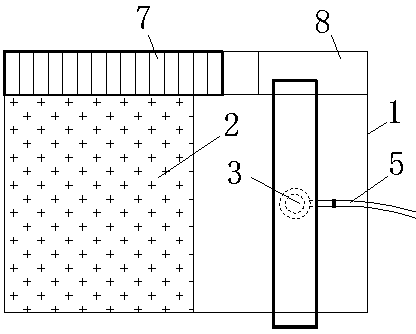
[0047] attached Figure 1-6 It can be seen that a sand filling device for silt geological release holes includes:

[0048] Use steel plates to weld the box body 1 and the steel slope 2;

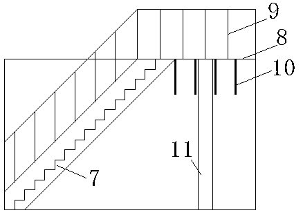
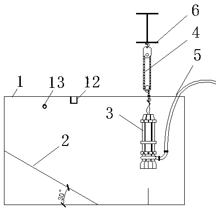
[0049] A shaped steel column 11 is arranged on the box body 1, and a main beam 6 and an electric hoist ring on the main beam are arranged on the top of the column;

[0050] A steel ladder 7, a platform 8, and platform legs 10 are provided on the box body 1;

[0051] A sand suction pump 3 is arranged in the box body 1;

[0052] Connect the conveying pipeline 5 to the water outlet of the sand suction pump 3, and use the electric hoist 4 to suspend the sand suction pump 3 into the box body 1;

[0053] The box body 1 is provided with a water inlet 13 .

[0054] The top of the box body 1 is welded with steel tie rods.

[0055] A sand filling method for a sand filling device in a...


PUM


Abstract

The invention relates to a sludge geology release hole sand filling device and method. A conveying pipeline is connected with a water outlet of a sand suction pump, and the sand suction pump is suspended in a box by an electric block. Medium coarse sand is loaded into the box body from the steel slope side by a loader, and water is pumped into the box from a water inlet; the electric hoist is adjusted to sink the sand suction pump into the water, sinking continues while the sand suction pump is started, and the mixture of medium coarse sand and water is transported to a long auger driller through a conveying pipe; the mixture is fed into a release hole by a drill stem, and the release hole is filled along with lifting of the long auger stem. The sludge geology release hole sand filling method ensures that the release hole does not fail during construction of a pipe pile and after construction is completed, reduces the construction cost and increases the construction speed; and by meansof cooperation with the long auger driller, it can be ensured that a release channel of excess pore water is effective for a long time during pipe pile construction and after construction.

Description

technical field [0001] The invention relates to a building construction method, in particular to a sand filling device and a sand filling method for silt geological release holes. Background technique [0002] Due to the characteristics of batch production, stable and reliable quality, high concrete strength of the pile body, high bearing capacity of a single pile, low price per unit bearing capacity, and strong adaptability to different geological conditions and different pile sinking processes, prestressed pipe piles are currently in use. It is widely popularized and applied in coastal areas of our country, and is replacing various traditional pile types in many areas, and has become the dominant pile type, which is welcomed by more and more designers. When disturbed, the soil equivalent to the volume of the pile is displaced to the surroundings, and the soil within a certain range at the tip of the pile and around the pile is subjected to undrained shear and large horizon...

Claims


Application Information

Patent Timeline
Patent Type & Authority Applications(China)
IPC IPC(8): E02D3/10
CPCE02D3/106
Inventor 李小青党楠苏术玉
Owner CHINA 22MCC GROUP CORP
Why Eureka
Try Eureka