
Calculation method for displacement deformation of existing tunnel caused by concentrated loads in tunnel

A concentrated load, existing tunnel technology, applied in tunneling, calculation, computer-aided design, etc., can solve the problem of inability to calculate the rotation and staggered deformation of shield tunnels, without considering the effect of segment ring joints, and less research on displacement deformation calculation And other issues

Active Publication Date: 2019-08-20
ZHEJIANG UNIV CITY COLLEGE +1
View PDF6 Cites 12 Cited by
  • Summary
  • Abstract
  • Description
  • Claims
  • Application Information

AI Technical Summary

Problems solved by technology

The main method of existing research is finite element numerical simulation, which is largely based on the modeling level, boundary conditions, and simulation of specific working conditions. There are few studies on the calculation of displacement and deformation of existing tunnels caused by concentrated loads
On the other hand, when considering the calculation of the theoretical solution of the deformation of the tunnel under the additional load, the shield tunnel is mostly simplified as a homogeneous elastic beam, and the joint effect between the segment rings is not considered, so the rotation and dislocation of the shield tunnel cannot be calculated. table deformation, the result deviates greatly from the actual deformation
[0004] To sum up, most of the studies on the displacement and deformation of existing tunnels caused by concentrated loads in tunnels focus on finite element numerical simulation, which is difficult to control the accuracy, and there are few methods for deriving theoretical solutions, and most of the calculation methods do not consider the tunnel Rotation and staggered deformation, the calculation results are not accurate enough, it is urgent to improve and optimize

Method used


Image

  • Calculation method for displacement deformation of existing tunnel caused by concentrated loads in tunnel
  • Calculation method for displacement deformation of existing tunnel caused by concentrated loads in tunnel
  • Calculation method for displacement deformation of existing tunnel caused by concentrated loads in tunnel

Examples


Embodiment Construction

[0088] The present invention will be further described below in conjunction with the examples. The description of the following examples is provided only to aid in the understanding of the present invention. It should be pointed out that for those skilled in the art, without departing from the principle of the present invention, some improvements and modifications can be made to the present invention, and these improvements and modifications also fall within the protection scope of the claims of the present invention.

[0089] This calculation method introduces a “shear stagger model” that considers rotation and staggering at the same time. It is considered that relative staggering and relative rotation angles will occur between adjacent segments at the same time, and the two together lead to the longitudinal deformation of the tunnel. Through the selection of parameters, the derivation of the additional load formula, and finally the use of the "shear displacement model" to ca...


PUM


Abstract

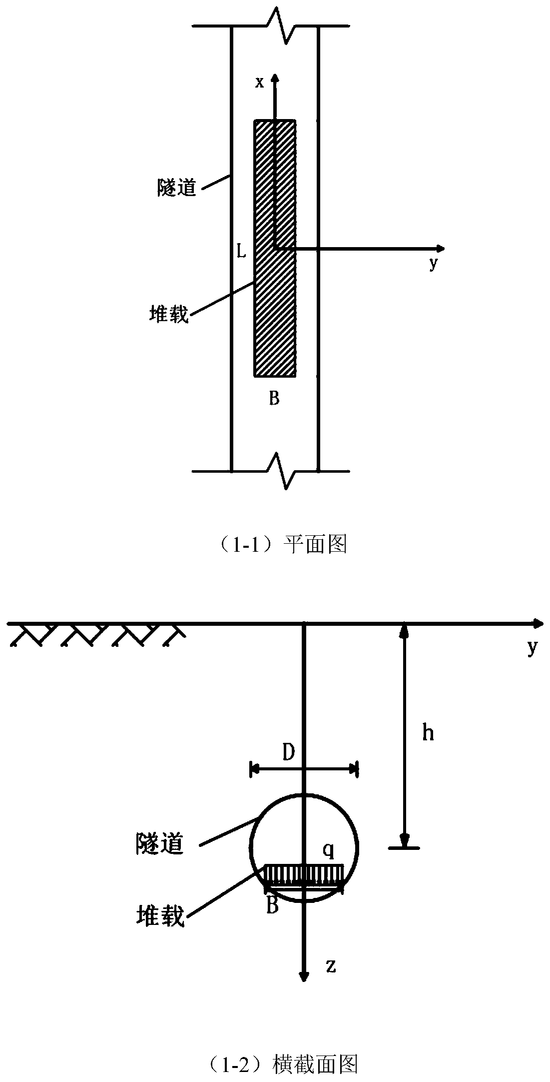
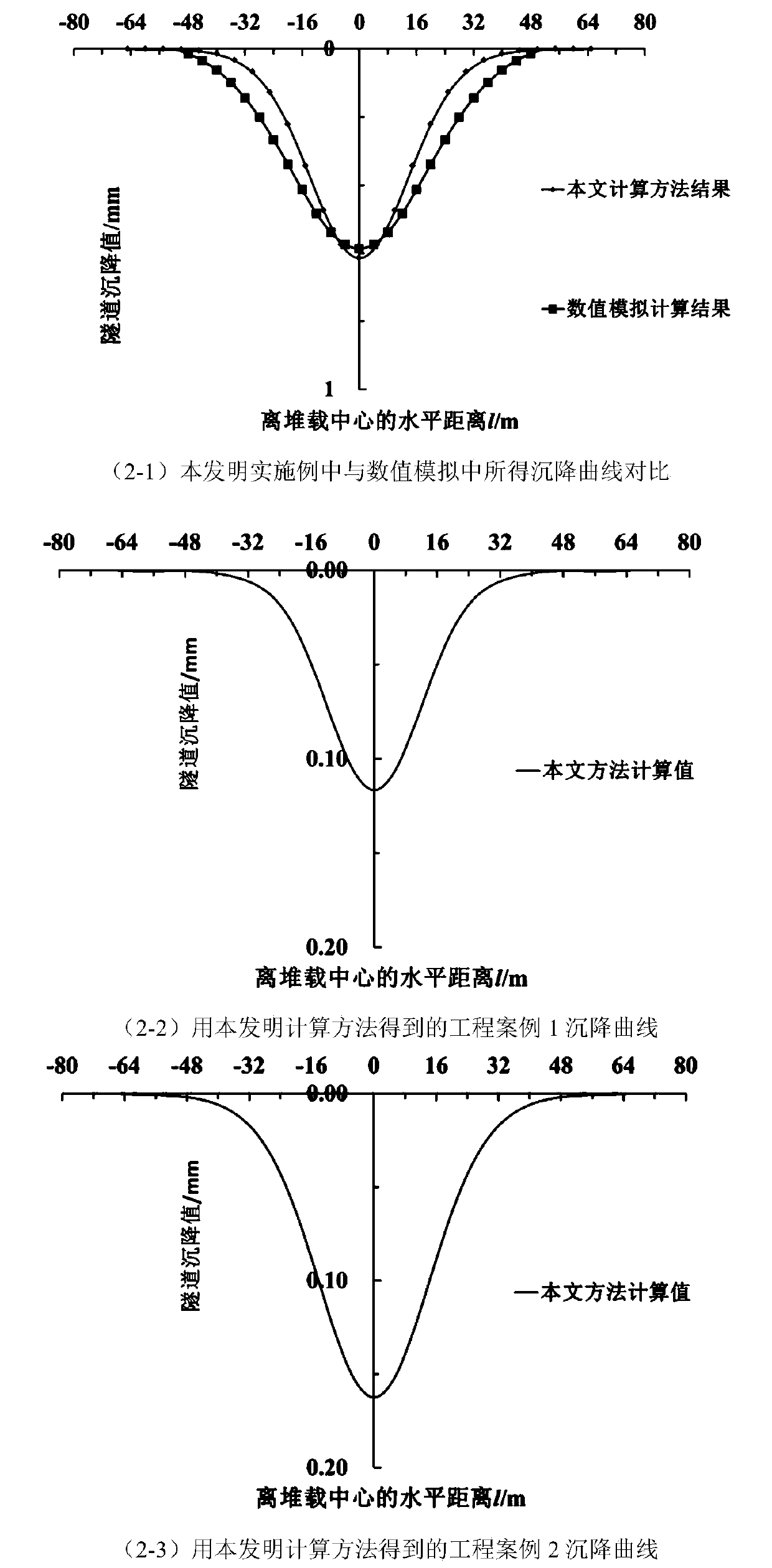
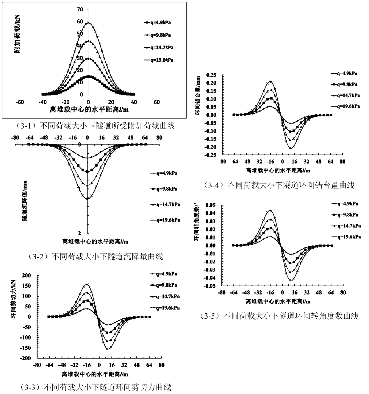
The invention relates to a calculation method for displacement deformation of an existing tunnel caused by concentrated loads in the tunnel. The calculation method comprises the following steps: step1) establishing a mechanical model of heap loading in the tunnel; 2) calculating an additional load by adopting a derivation formula of a Peck formula; and 3) calculating tunnel settlement and deformation. The method has the beneficial effects that the joint effect between the tunnel rings is considered, a shear staggered platform model is introduced, meanwhile, shear deformation and staggered platform deformation between the tunnel rings are analyzed, the shear deformation and the staggered platform deformation are more consistent with an actual tunnel structure stress deformation mode, and atunnel settlement and deformation calculation result is more accurate; in the calculation method, the modeling is simple and clear; the calculation process of the soil body additional load is simpleand easy to understand, and the finally obtained load normal distribution function f (x) involves few parameters and is convenient to calculate and analyze.

Description

technical field [0001] The invention belongs to the technical field of underground engineering, and in particular relates to a method for calculating the displacement of an existing tunnel caused by concentrated load in the tunnel, which is suitable for tunnel displacement and deformation under the concentrated load caused by piled load or vertical pipe jacking inside the shield tunnel value calculation. Background technique [0002] In recent years, the development of underground engineering construction has made the limited urban shallow ground space more and more crowded, and a large number of construction projects adjacent to the existing shield tunnels have been continuously carried out. Among them, the shield tunneling and foundation pit excavation projects adjacent to the existing tunnel will have an unloading effect on the soil above the existing tunnel, resulting in the floating deformation of the existing tunnel, causing segment cracking, joint opening, Bolt failu...

Claims


Application Information

Patent Timeline
Patent Type & Authority Applications(China)
IPC IPC(8): G06F17/50E21D9/00
CPCE21D9/00G06F2111/10G06F30/23G06F30/20Y02T90/00
Inventor 魏纲齐永洁吴华君王霄章丽莎尹鑫晟吴俊峰张鑫海
Owner ZHEJIANG UNIV CITY COLLEGE
Learn More