
An air duct structure of a power distribution cabinet and a power distribution cabinet thereof

A technology for power distribution cabinets and air ducts, which is applied in the substation/power distribution device shell, substation/switchgear cooling/ventilation, electrical components, etc. problems, to achieve the effect of ensuring ventilation and heat dissipation, convenient use, and preventing blockage

Active Publication Date: 2020-04-28
ANHUI QUEUE ELECTRIC
View PDF1 Cites 0 Cited by
  • Summary
  • Abstract
  • Description
  • Claims
  • Application Information

AI Technical Summary

Problems solved by technology

[0002] In the prior art, a high-efficiency heat dissipation power distribution cabinet with the application number "201611050184.8" includes a cabinet body and a cabinet door. The cabinet door is movably connected to the cabinet body, and the top and bottom of the cabinet body are provided with ventilation structures. , the other three sides of the cabinet body except the side of the cabinet door are provided with heat dissipation holes, and the upper edge of the heat dissipation holes has a water-retaining edge extending outward. The high-efficiency heat dissipation distribution cabinet makes The cabinet forms a natural ventilation channel from bottom to top, which can achieve the purpose of heat dissipation without using a radiator connected to an external power supply. At the same time, it can also prevent rainwater from intruding into the power distribution cabinet, which will damage the electrical components in the cabinet and affect the use.
[0003] However, there are still relatively obvious defects in its use: 1. The above-mentioned device mainly dissipates heat through the heat dissipation holes, and outside the heat dissipation holes, only a water-retaining edge is inclined to prevent rain, and its actual effect is very limited. As we all know , thunderstorms and storms occur frequently in summer, if the heat dissipation holes are not completely covered, the rainwater will still enter the power distribution cabinet under the blowing belt of the strong wind, causing damage to the electrical components in it; 2. The above-mentioned devices mainly use natural ventilation. The method is applicable when the temperature is suitable, but in the continuous high temperature and hot summer season, the heat dissipation efficiency of relying on natural ventilation is very low. Long-term use will cause spontaneous combustion and burnout due to the continuous overheating of internal components.

Method used


Image

  • An air duct structure of a power distribution cabinet and a power distribution cabinet thereof
  • An air duct structure of a power distribution cabinet and a power distribution cabinet thereof
  • An air duct structure of a power distribution cabinet and a power distribution cabinet thereof

Examples


Embodiment Construction

[0026] The following will clearly and completely describe the technical solutions in the embodiments of the present invention with reference to the accompanying drawings in the embodiments of the present invention. Obviously, the described embodiments are only some, not all, embodiments of the present invention. Based on the embodiments of the present invention, all other embodiments obtained by persons of ordinary skill in the art without making creative efforts belong to the protection scope of the present invention.

[0027] see Figure 1-5 , the present invention provides a technical solution:

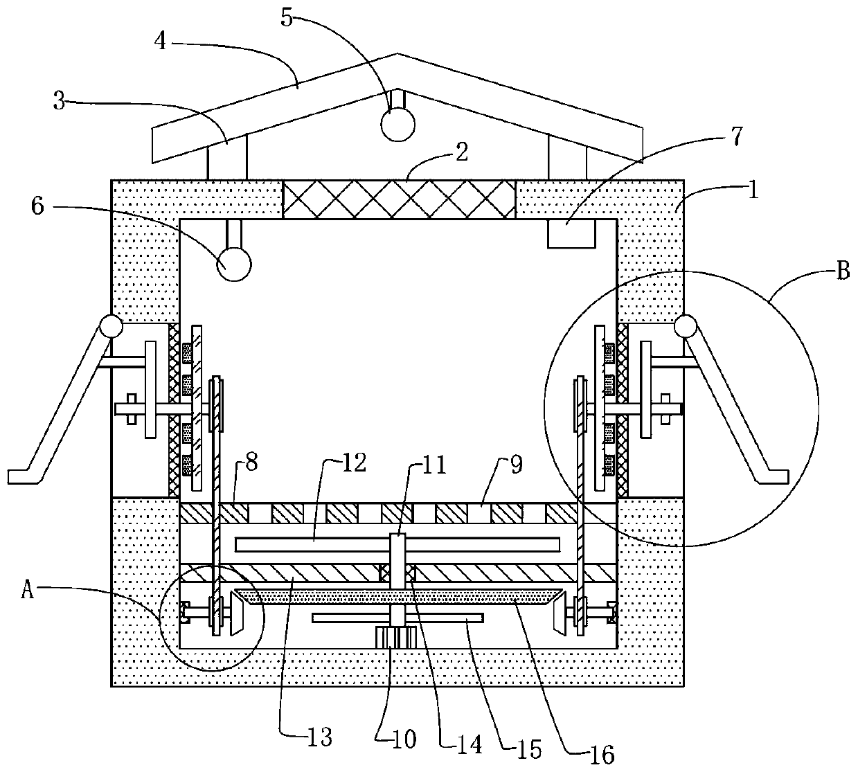
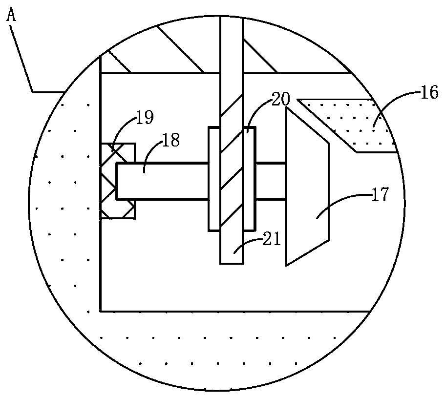
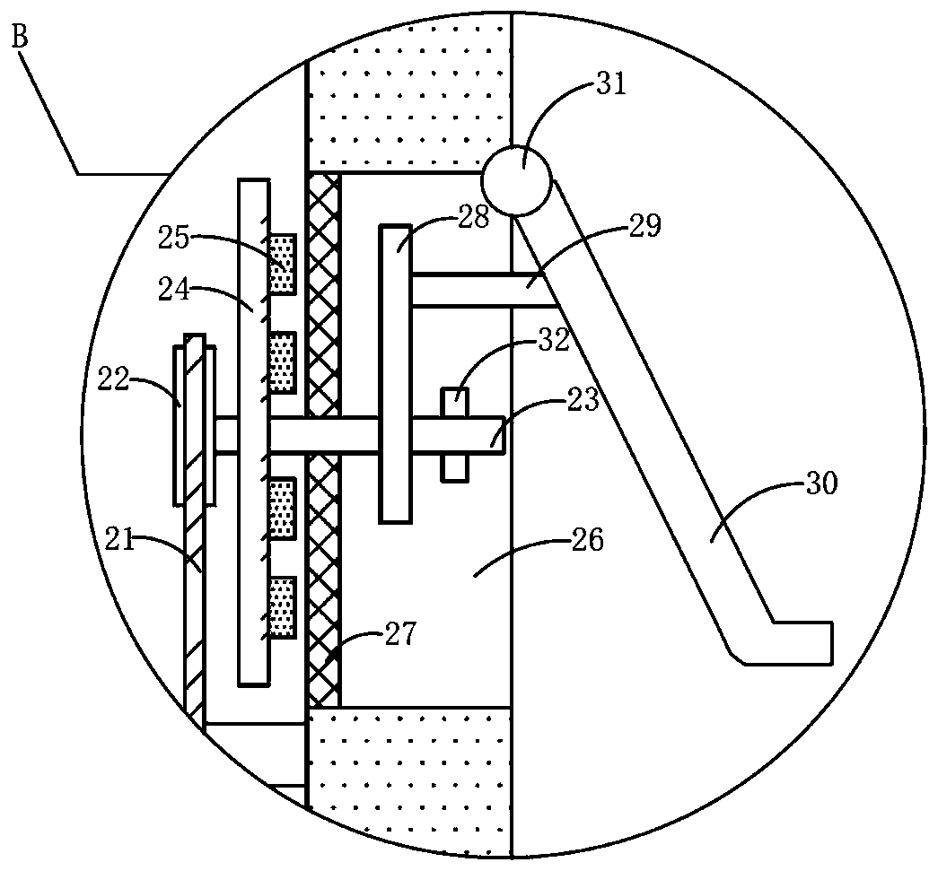
[0028] An air duct structure of a power distribution cabinet, comprising a cabinet body 1, an upper ventilation screen frame 2 is arranged on the cabinet body 1, and the upper ventilation screen frame 2 is used for ventilation, and the gauze installed in the screen frame can prevent dust in the outside air Impurities and the like enter the inside of the cabinet body 1, and the out...


PUM


Abstract

The invention discloses an air duct structure for a power distribution cabinet and the power distribution cabinet. The cabinet comprises a cabinet body, and an upper ventilation net frame is arrangedon the cabinet body; a humidity detector is arranged at the side, close to the cabinet body, of a rainproof ceiling; main heat dissipation blades are fixedly arranged at one end, far away from the motor, of a main shaft; a cleaning rod is fixedly arranged on a lead screw in a penetrating mode, and brush bristles are arranged on the cleaning rod; a filter screen is arranged in a heat dissipation window, and a rain baffle is fixedly arranged on a push rod; and the rain baffle is arranged on the cabinet body in a hinged mode through a hinge. The invention provides the air duct structure for the power distribution cabinet. Two heat dissipation systems are arranged in the shell; a power structure can be automatically started at high temperature to assist in heat dissipation, and the rain baffleis movably arranged on the heat dissipation window of the cabinet body; the cabinet body can be automatically opened to strengthen ventilation in sunny days and can be automatically closed in rainy days to prevent rainwater from inclining into the cabinet body. The invention also discloses the power distribution cabinet with the above air duct structure, and the cabinet is good in using effect and quite worthy of popularization.

Description

technical field [0001] The invention relates to the technical field of power distribution cabinets, in particular to an air duct structure of a power distribution cabinet and a power distribution cabinet thereof. Background technique [0002] In the prior art, a high-efficiency heat dissipation power distribution cabinet with the application number "201611050184.8" includes a cabinet body and a cabinet door. The cabinet door is movably connected to the cabinet body, and the top and bottom of the cabinet body are provided with ventilation structures. , the other three sides of the cabinet body except the side of the cabinet door are provided with heat dissipation holes, and the upper edge of the heat dissipation holes has a water-retaining edge extending outward. The high-efficiency heat dissipation distribution cabinet makes The cabinet forms a natural ventilation channel from bottom to top, which can achieve the purpose of heat dissipation without using a radiator connected...

Claims


Application Information

Patent Timeline
Patent Type & Authority Patents(China)
IPC IPC(8): H02B1/28H02B1/30H02B1/56
CPCH02B1/28H02B1/306H02B1/565
Inventor 石敏王建郭玉文单钜程葛学章刘凯楚卫民侯骏张惠忠侯金华张雅雯黄健
Owner ANHUI QUEUE ELECTRIC
Learn More