
A cave-based fusion system for different-plane perspective correction

A perspective correction and out-of-plane technology, applied in the field of image processing, to achieve the effect of strong practicability, not easy to tear, and small investment

Active Publication Date: 2021-01-08
德马吉国际展览有限公司
View PDF4 Cites 0 Cited by
  • Summary
  • Abstract
  • Description
  • Claims
  • Application Information

AI Technical Summary

Problems solved by technology

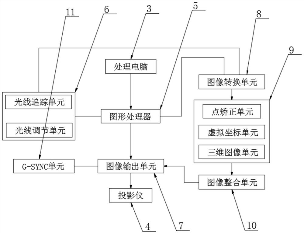
[0005] In order to overcome the above-mentioned defects of the prior art, an embodiment of the present invention provides a CAVE-based different-plane perspective correction and fusion system. By using a graphics processor to convert an image into an editable image, the point correction unit pulls the control in the editable image point, make the lines in the image coincide or be parallel to the image content, correct the image, the virtual coordinate unit generates the corresponding virtual space projector coordinates according to the image content and the direction of the projector, and the 3D image unit generates real-time coordinates according to the projector coordinates Generate stereoscopic images of the corresponding projection surface, and the number of processing computers and graphics processors is the same as the number of projection surfaces. Multiple processing computers are connected by synchronous cards, and the system can send commands within the minimum response time, so that the system after perspective correction The graphics will not be deformed and distorted, the vertical lines in the image can match the image content, and the investment is small, the operation is simple and easy to go online, and the practicability is strong

Method used


Image

  • A cave-based fusion system for different-plane perspective correction
  • A cave-based fusion system for different-plane perspective correction

Examples


Embodiment 1

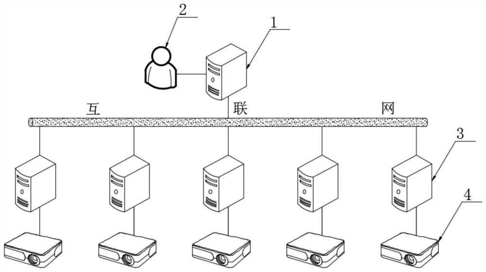
[0027] like Figure 1-2 A CAVE-based different-plane perspective correction fusion system shown includes a server 1, an operating terminal 2, a processing computer 3 and a projector 4, and the number of the processing computers 3 and projectors 4 is set to multiple, and multiple The processing computer 3 and the projector 4 are connected to each other, the server 1 is connected to a plurality of processing computers 3 through the Internet, and the plurality of processing computers 3 are connected by a synchronization card;

[0028] A plurality of said processing computers 3 are respectively responsible for the image information in different projection planes, and complete the perspective correction of the image information in different projection planes;

[0029] The operation terminal 2 is connected to the server 1, and the operation terminal 2 is a user's command input terminal, which is used to input control commands to the operation of the server 1, and also transmits imag...

Embodiment 2

[0039] Such as Figure 1-2 Shown is a different-plane perspective correction and fusion system based on CAVE, the number of processing computers 3 and projectors 4 is customized according to the number of display surfaces of CAVE;

[0040] When the number of display surfaces of the CAVE system is increased, the number of processing computers 3 and projectors 4 is also increased. Synchronized with the CAVE system, the newly connected processing computer 3 uses a synchronization card to connect with the previous processing computer 3, and through the Internet Connect with server 1, so that each display surface in the CAVE system can have an independent different-surface image perspective correction module, and there will be no tearing or deformation of a single screen during the display process;

[0041] The multiple processing computers 3 are responsible for the image information in different projection planes respectively, and complete the perspective correction of the image i...

Embodiment 3

[0043] Such as Figure 1-2 As shown in a CAVE-based different-plane perspective correction and fusion system, the number of graphics processors 5 in the processing computer 3 can be set to multiple, specifically set to multi-card crossfire.

[0044] By processing the expansion interface on the motherboard of the computer 3, the number of graphics processors 5 is increased, and multi-card crossfire is performed, so that the image conversion unit 8, the light processing unit 6 and the correction unit 9 can obtain higher graphics performance support during work. , the speed when completing the image different-plane perspective correction can be improved. After the image conversion unit 8 receives the image information, it reads the image information and converts the image into an editable image, and uses the point correction unit to pull the editable image. The control points in the image make the lines in the image coincide or parallel to the image content, and the image is corr...


PUM


Abstract

The invention discloses a different-plane perspective correction fusion system based on CAVE, and specifically relates to the technical field of image processing. The system comprises a server, an operation end, a plurality of processing computers and a plurality of projectors. The plurality of processing computers and the plurality of projectors are mutually connected, the server is connected with the plurality of processing computers through the Internet, and the plurality of processing computers are connected through a synchronous card. The plurality of processing computers are respectivelyresponsible for image information in different projection surfaces to complete perspective correction of the image information in the different projection surfaces. The operation end is connected with the server, is a command input end of a user, and is used for inputting a control command to the operation of the server. According to the system, the perspective corrected graph does not have the phenomenon of deformation distortion, the vertical line in the image can be matched with the image content, the invested capital is small, the operation is simple, the on-line operation is easy, and the practicability is strong.

Description

technical field [0001] The present invention relates to the technical field of image processing, and more specifically, the present invention relates to a CAVE-based heteroplane perspective correction and fusion system. Background technique [0002] CAVE is represented by VR-Platform CAVE virtual reality display system. CAVE is an immersive virtual reality display system based on projection, which is characterized by high resolution, strong immersion, and good interactivity. The principle of the CAVE immersive virtual reality display system is relatively complicated. It is based on computer graphics and perfectly integrates high-resolution stereoscopic projection display technology, multi-channel visual synchronization technology, audio technology, and sensor technology. Thus, a fully immersive virtual environment surrounded by three-dimensional projection screens for multiple people is generated. [0003] Since the rear projection hard screen structure of the multi-channe...

Claims


Application Information

Patent Timeline
Patent Type & Authority Patents(China)
IPC IPC(8): H04N9/31
CPCH04N9/3147H04N9/3185
Inventor 王翔师欣欣许梦捷蒋萍
Owner 德马吉国际展览有限公司
Learn More