A garden engineering garbage disposal device
A garbage disposal device and garbage disposal technology, applied in mixers with rotating stirring devices, transportation and packaging, chemical/physical processes, etc., can solve the problem of landfill disposal of untreated garbage, increase of garbage disposal costs, violation of improvement Environmental problems, to curb the growth of weeds, save manpower, maintain the effect of soil moisture
- Summary
- Abstract
- Description
- Claims
- Application Information
AI Technical Summary
Problems solved by technology
Method used
Image
Examples
specific Embodiment approach 1
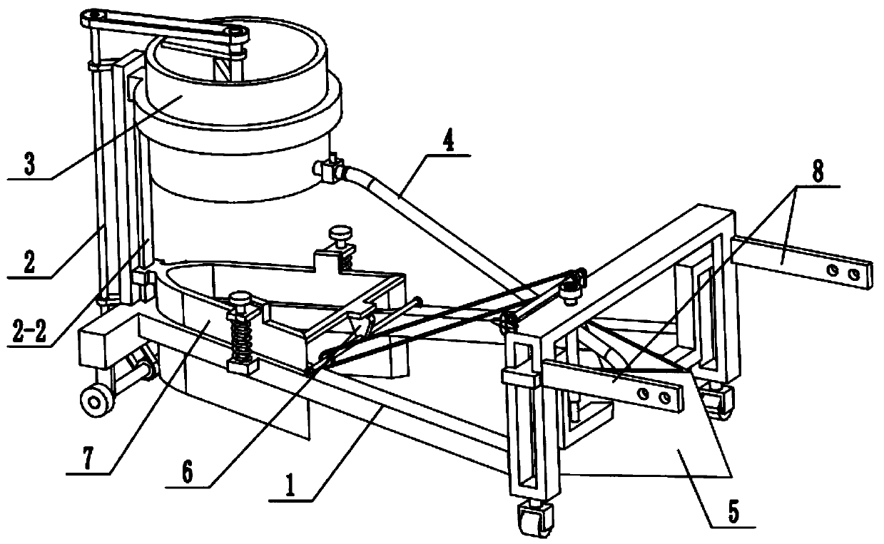
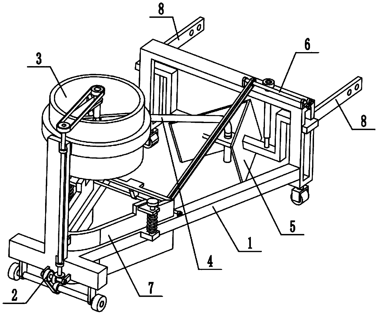
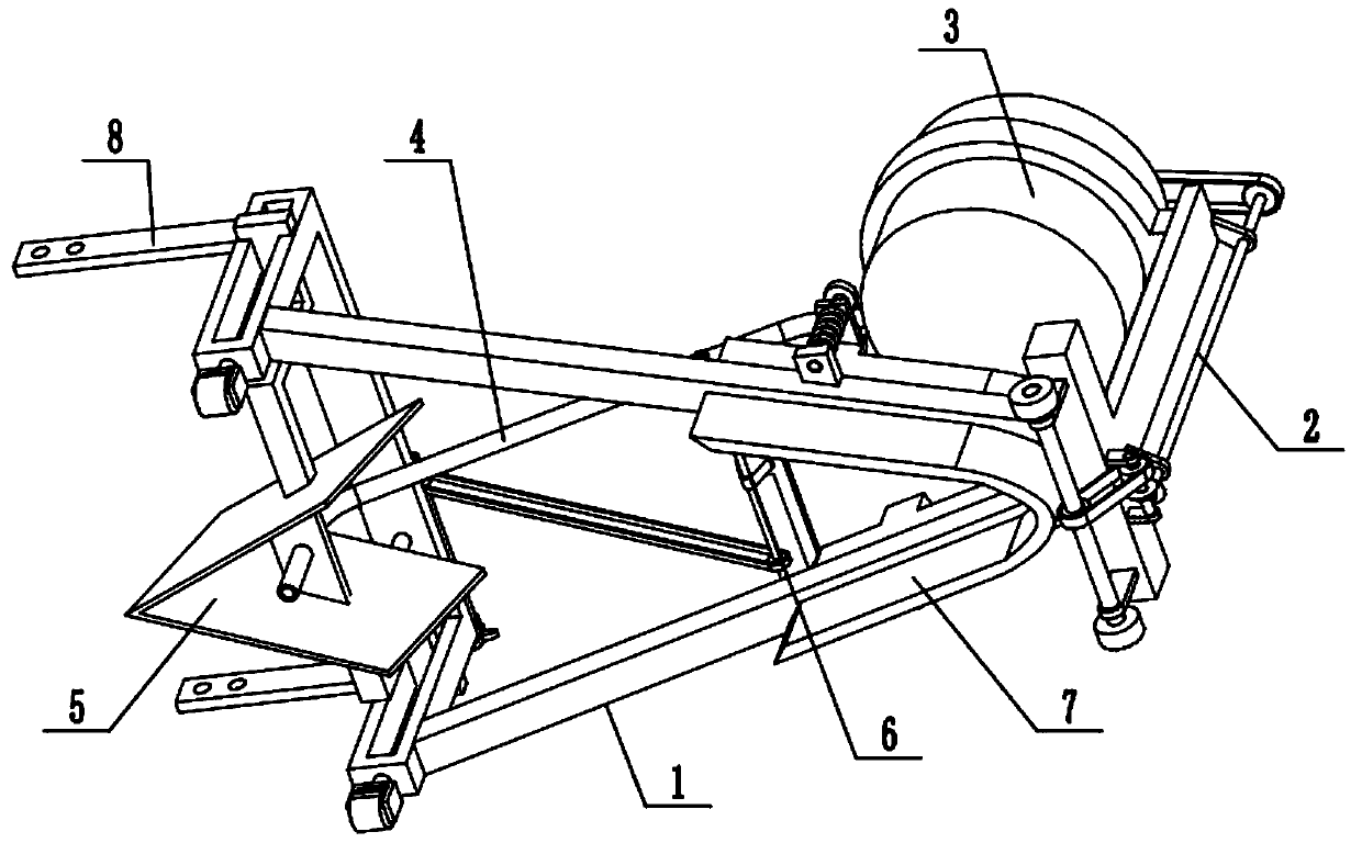
[0030] Combine below Figure 1-11 Describe this embodiment, a garden engineering waste treatment device, including a frame 1, a linkage wheel set 2, a waste treatment mixing box 3, a retractable material guide hose 4, a hose guide soil removal mechanism 5, and a transmission wheel assembly 6 , Soil restoration assembly 7 and fixed plate 8, described linkage wheel set 2 is fixedly connected to the left end of frame 1, and garbage disposal mixing box 3 is fixedly connected to the upper end of linkage wheel set 2, and the lower end of linkage wheel set 2 is connected to the frame 1 transmission connection, the upper end of the linkage wheel set 2 is connected with the garbage treatment mixing box 3, and the two ends of the retractable material guide hose 4 are respectively connected with the garbage treatment mixing box 3 and the hose guiding soil removal mechanism 5. The right end of the material hose 4 is inclined downward, and the hose guiding soil moving mechanism 5 is arrang...
specific Embodiment approach 2
[0032] Combine below Figure 1-11 To illustrate this embodiment, the frame 1 includes a V-shaped underframe 1-1, a vertical sliding frame 1-2, a universal wheel 1-3, a wheel seat 1-4, a wheel frame plate 1-5, and a wheel shaft 1- 6. Roller 1-7, driving pulley 1-8 and V-shaped chute 1-9; the V-shaped mouth of V-shaped bottom frame 1-1 is open towards the right end, and the front and rear ends of the right end of V-shaped bottom frame 1-1 are respectively A vertical sliding frame 1-2 is fixedly connected, the lower ends of the two vertical sliding frames 1-2 are respectively connected to a universal wheel 1-3 by rotation, and the left end of the V-shaped chassis 1-1 is fixedly connected to the wheel seat 1-4, the wheel seat The lower end of 1-4 is fixedly connected to two wheel frame plates 1-5, the wheel shaft 1-6 is rotatably connected to the two wheel frame plates 1-5 through bearings with seats, and the two ends of wheel shaft 1-6 are respectively fixedly connected to a roll...
specific Embodiment approach 3
[0034] Combine below Figure 1-11 To illustrate this embodiment, the linkage wheel set 2 includes a vertical frame plate 2-1, a trapezoidal slide rail 2-2, an annular fixed frame 2-3, a shaft frame plate 2-4, a transmission shaft 2-5, and a driving pulley 2-6, driven bevel gear 2-7, driving bevel gear 2-8, driven pulley 2-9, drive shaft 2-10 and horizontal frame plate 2-11; vertical frame plate 2-1 is fixedly connected to the wheel On the seat 1-4, the trapezoidal slide rail 2-2 is fixedly connected to the right end surface of the vertical frame plate 2-1, the ring-shaped fixed frame 2-3 is fixedly connected to the upper end of the vertical frame plate 2-1, and the garbage disposal mixing box 3 is fixed Connected in the annular fixed frame 2-3, the vertical frame plate 2-1 is fixedly connected with two shaft frame plates 2-4, and the transmission shaft 2-5 is rotatably connected to the two shaft frame plates 2-4 through a bearing with seat. The driving pulley 2-6 and the driv...
PUM
 Abstract
Description
Claims
Application Information
 - R&D
- Intellectual Property
- Life Sciences
- Materials
- Tech Scout
- Unparalleled Data Quality
- Higher Quality Content
- 60% Fewer Hallucinations
Browse by: Latest US Patents, China's latest patents, Technical Efficacy Thesaurus, Application Domain, Technology Topic, Popular Technical Reports.
© 2025 PatSnap. All rights reserved.Legal|Privacy policy|Modern Slavery Act Transparency Statement|Sitemap|About US| Contact US: help@patsnap.com


