Anti-blocking aeration head

An aeration head and anti-blocking technology, applied in biological sludge treatment and other directions, can solve problems such as blockage of aeration discs, and achieve the effect of preventing sludge from entering the exhaust hole and blocking the aeration head.

Pending Publication Date: 2019-08-23
广州华功环保技术有限公司
View PDF0 Cites 7 Cited by
  • Summary
  • Abstract
  • Description
  • Claims
  • Application Information

AI Technical Summary

Problems solved by technology

When the compressed air is stopped, the rubber on the surface of the aeration disc will retract, and a short negative pressure will be generated in

Method used


Image

  • Anti-blocking aeration head
  • Anti-blocking aeration head
  • Anti-blocking aeration head

Examples


Example Embodiment

[0021] Example 1:

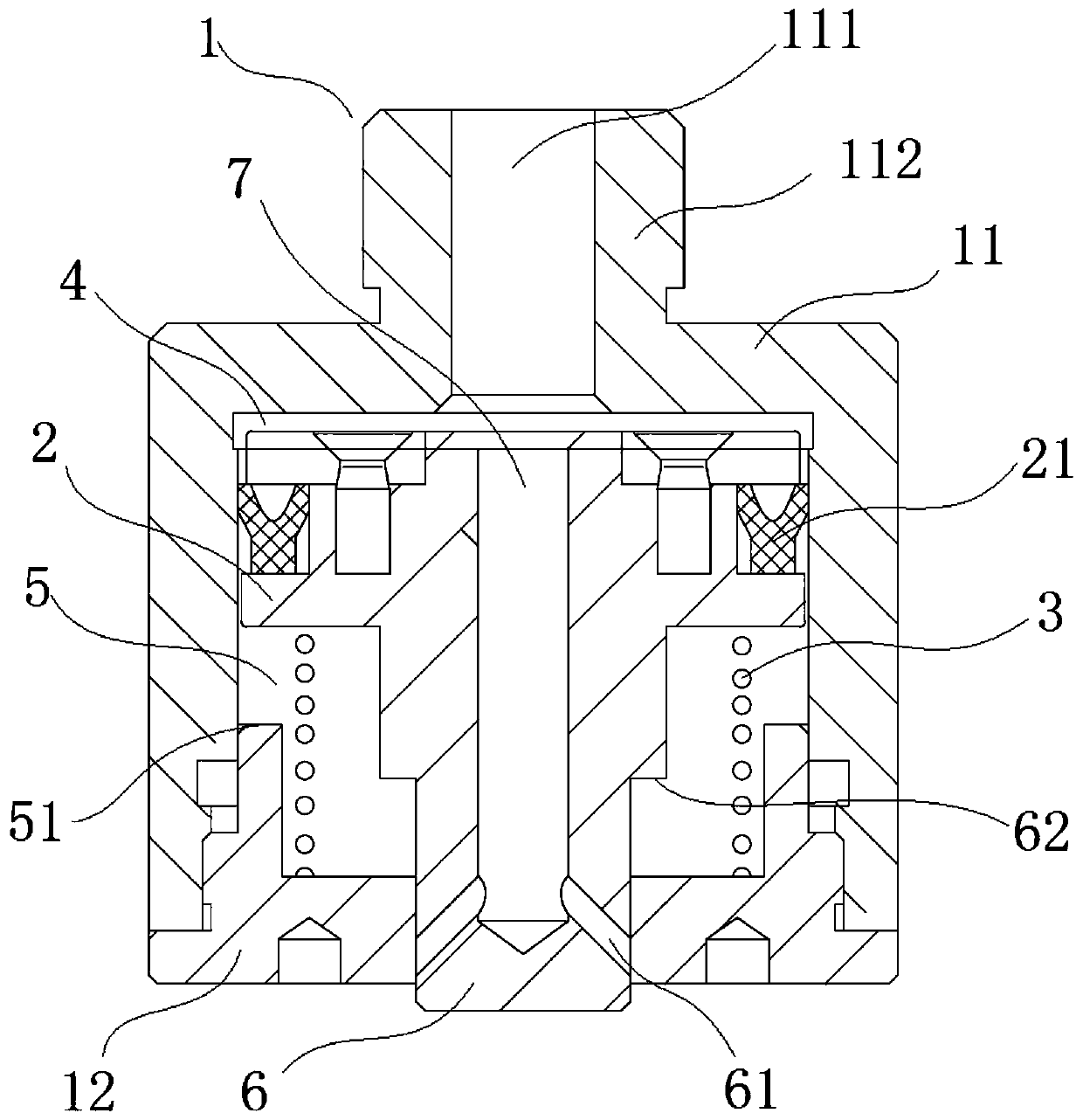
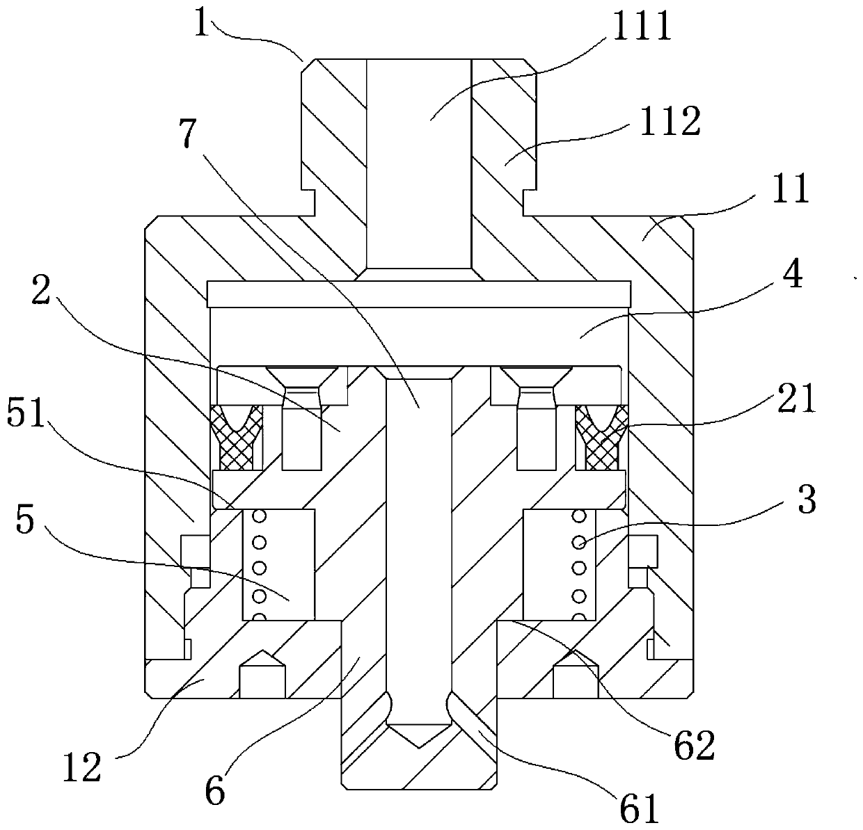
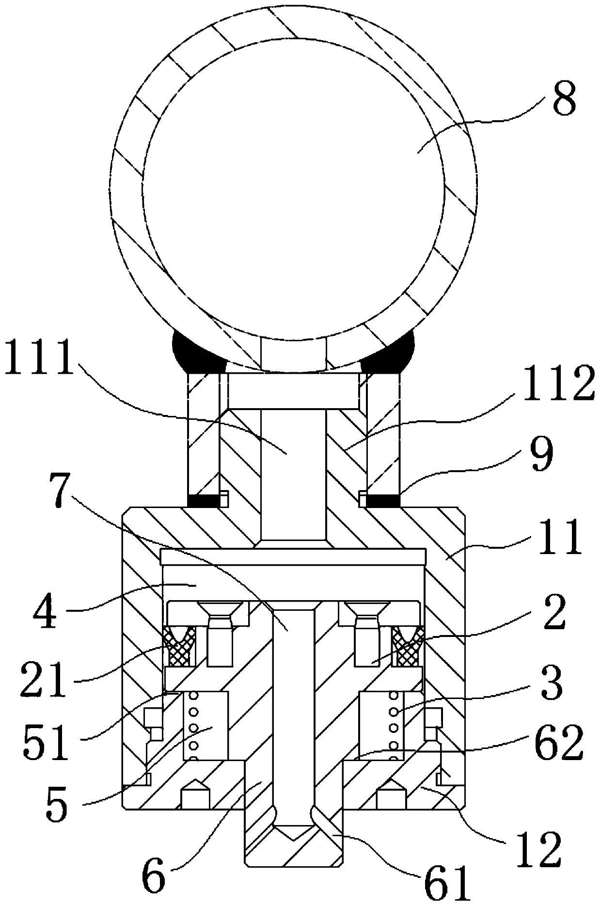
[0022] like Figures 1 to 3 As shown, an anti-blocking aeration head includes a cylinder body 1, a piston 2 and a return spring 3, the piston 2 is arranged in the cylinder body 1, and the cylinder body 1 is divided into a cavity A4 and a cavity B5, and the cavity A4 and the cavity B5 The air inlet 111 of the barrel 1 is connected, and the return spring 3 is arranged in the cavity B5; it also includes the piston rod 6 arranged in the cavity B5, and the end of the barrel 1 opposite to the air inlet 111 is provided with a piston rod for installation. 6 mounting holes, one end of the piston rod 6 is connected to the piston 2, and the other end is penetrated in the mounting hole; a blind hole channel 7 is provided from one end of the piston 2 to the other end of the piston rod 6, and the opening end of the blind hole channel 7 Located at one end of the cavity A4 , the piston rod 6 is provided with an exhaust hole 61 communicating with the blind hole channel 7 ,...

Example Embodiment

[0029] Example 2

[0030] This embodiment is similar in structure to other parts of Embodiment 1, the difference is that the exhaust hole 61 is arranged obliquely, and the gas outlet end of the exhaust hole 61 is inclined towards the end away from the piston 2 . As preferably, a plurality of exhaust holes 61 are provided, and a plurality of exhaust holes 61 are arranged obliquely, that is, they are inclined toward the direction in which the piston rod 6 extends into the mud, so that the mud can be further prevented from entering the exhaust holes 61 to the blind holes. In the channel 7; when the piston rod 6 moves back to the installation hole, even if there is mud outside the vent hole 61, on the one hand, the vent hole 61 is inclined downward, and there is a surplus of compressed air at the same time, and the mud cannot enter the exhaust port. On the other hand, the silt on the outer wall of the piston rod 6 will also be scraped off by the mounting hole; through the above tw...

Example Embodiment

[0031] Example 3

[0032] This embodiment is similar in structure to other parts of Embodiment 2. The different cylinder body 1 includes a cylinder body 11 and an end cover 12, and the end cover 12 is connected to the cylinder body 11 through a threaded seal; the air inlet 111 is arranged on the cylinder body 11, and Holes are provided on the end cover 12 . Cylinder 1 includes cylinder body 11 and end cover 12, which is convenient for disassembly, installation and maintenance. When piston 2 or Y-shaped sealing ring 21 is damaged, open end cover 12, and piston 2 can be taken out for replacement or maintenance.


PUM


Abstract

The invention relates to the technical field of sludge treatment, and particularly relates to an anti-blocking aeration head. The anti-blocking aeration head comprises a cylinder body, a piston and areset spring, wherein the piston is arranged in the cylinder body and divides the cylinder body into a cavity A and a cavity B, the cavity A communicates with an air inlet hole of the cylinder body, and the reset spring is arranged in the cavity B; the anti-blocking aeration head further comprises a piston rod arranged in the cavity B, wherein a mounting hole used for installing the piston rod isformed in one end, opposite to the air inlet hole, of the cylinder body, one end of the piston rod is connected with the piston, and the other end of the piston rod penetrates through the mounting hole; and a blind hole channel is formed from one end of the piston to the other end of the piston rod, wherein the open end of the blind hole channel is located at one end where the cavity A is located,exhaust holes communicating with the blind hole channel are formed in the piston rod, and the exhaust holes are located in the mounting hole of the cylinder body. According to the anti-blocking aeration head, sludge can be effectively prevented from entering the exhaust holes, so that the aeration head is prevented from being blocked.

Description

technical field [0001] The invention relates to the technical field of sludge treatment, in particular to an anti-blocking aeration head. Background technique [0002] Sludge aerobic fermentation is a harmless, volume-reducing, and stabilized sludge comprehensive treatment technology, also known as aerobic composting technology. It uses the action of aerobic thermophilic bacteria and thermophilic bacteria to decompose the organic matter in the sludge to form a substance similar to humus soil. The heat generated during the metabolic process can raise the temperature of the stockpile layer to above 55°C, which can effectively kill pathogens, parasite eggs and viruses, and increase the fertilizer content of sludge. Aerobic fermentation technology has attracted people's attention because of its low investment and low operating costs, and has a wide range of applications. [0003] The surface of the traditional aeration disc is covered with film. During aeration, the compressed...

Claims


Application Information

Patent Timeline
IPC IPC(8): C02F11/02
CPCC02F11/02
Inventor 何四清
Owner 广州华功环保技术有限公司
Why Eureka
Try Eureka