High-efficiency and energy-saving converter

A high-efficiency energy-saving, converter technology, applied in the manufacture of converters, etc., can solve the problems of left and right shaking, fast heat energy consumption, slow heat efficiency, etc., and achieve the effects of accelerating contact, reducing energy consumption, and improving efficiency

Active Publication Date: 2019-08-23
浙江琰大新材料有限公司
View PDF4 Cites 3 Cited by
  • Summary
  • Abstract
  • Description
  • Claims
  • Application Information

AI Technical Summary

Problems solved by technology

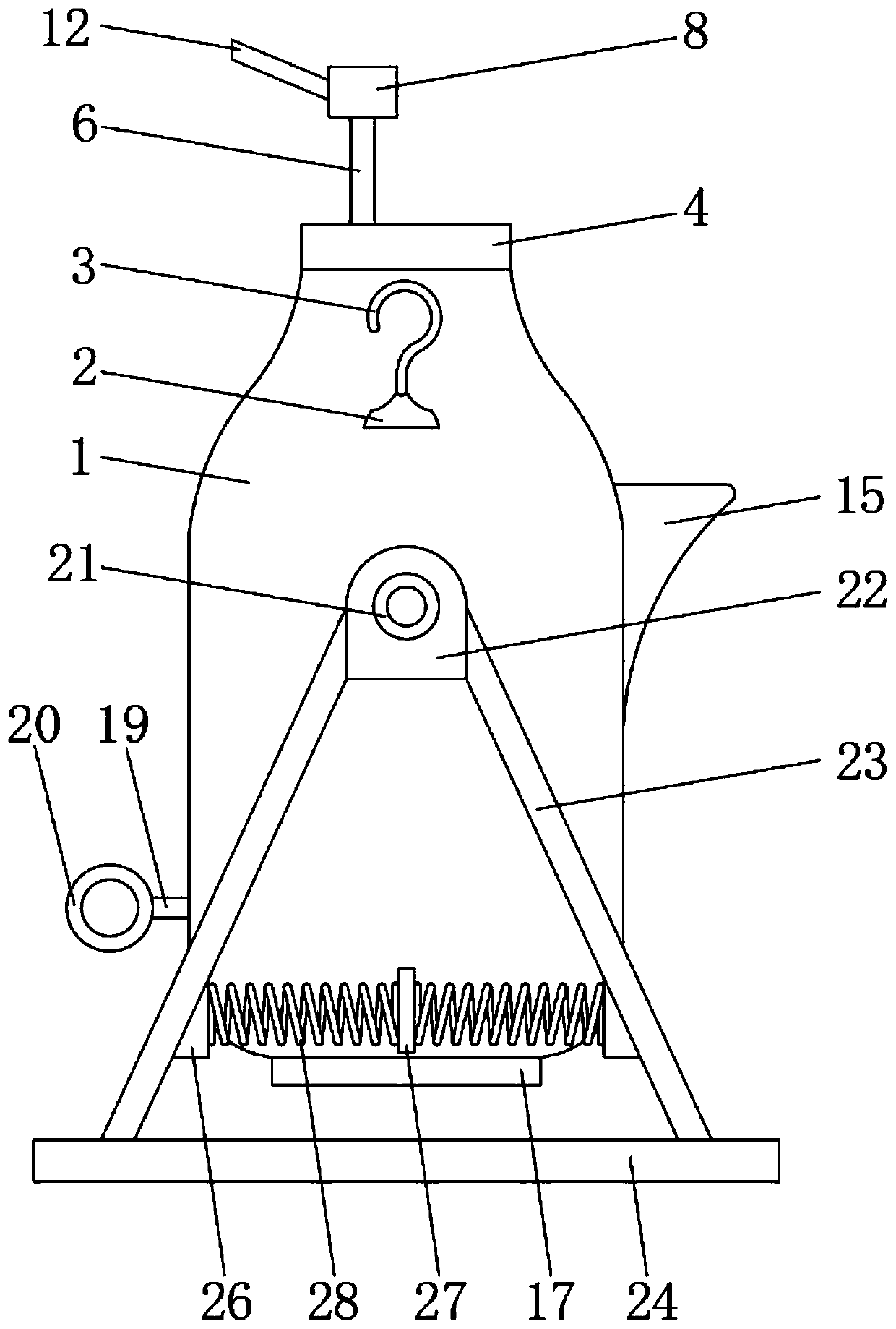
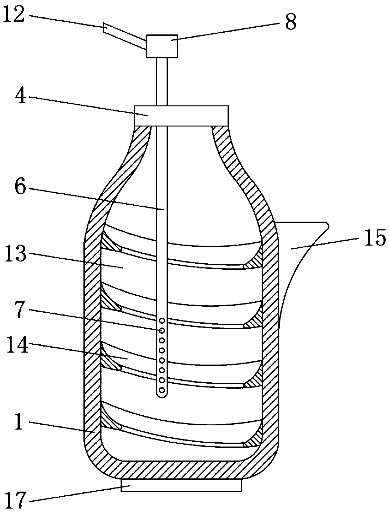
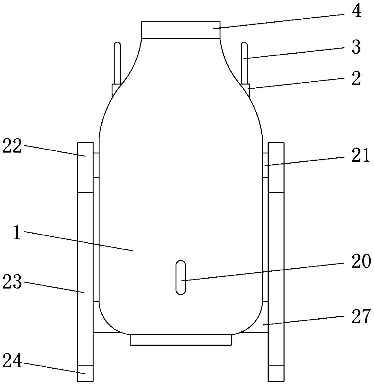
[0003] The main purpose of the present invention is to provide a high-efficiency and energy-saving converter, which can effectively solve the problems in the background technology that the thermal efficiency is relatively slow, resulting in rapid thermal energy consumption and the lack of vertical positioning mechanism, resulting in left and right shaking

Method used


Image

  • High-efficiency and energy-saving converter
  • High-efficiency and energy-saving converter
  • High-efficiency and energy-saving converter

Examples


Embodiment Construction

[0023] In order to make the technical means, creative features, goals and effects achieved by the present invention easy to understand, the present invention will be further described below in conjunction with specific embodiments.

[0024] In the description of the present invention, it should be noted that the terms "upper", "lower", "inner", "outer", "front end", "rear end", "both ends", "one end", "another end" The orientation or positional relationship indicated by etc. is based on the orientation or positional relationship shown in the drawings, and is only for the convenience of describing the present invention and simplifying the description, rather than indicating or implying that the referred device or element must have a specific orientation, use a specific Azimuth configuration and operation, therefore, should not be construed as limiting the invention. In addition, the terms "first" and "second" are used for descriptive purposes only, and should not be understood ...


PUM


Abstract

The invention discloses a high-efficiency and energy-saving converter. The high-efficiency and energy-saving converter comprises a converter body. A converter body port lantern ring is fixedly installed on the upper surface of the converter body. An oxygen pipe fixing base is fixedly installed on the inner side of the converter body port lantern ring. An oxygen injection pipe is arranged on the inner side of the oxygen pipe fixing base. A backflow prevention device is fixedly installed on the outer surface of the upper end of the oxygen injection pipe. An oxygen input pipe is fixedly installedon the outer surface of one side of the backflow prevention device. A converter body inner chamber is arranged inside the converter body. A rotary threaded block is arranged on the inner wall of theconverter body. A molten iron pouring nozzle is fixedly installed on the outer surface of one side of the converter body. A molten iron pouring outlet is formed in the inner side of the molten iron pouring nozzle. A pull rod connecting rod is fixed to the outer surface of the other side of the converter body. With the high-efficiency and energy-saving converter, energy consumption is reduced, theefficiency of steel making is improved, the converter body is prevented from shaking, and the converter body is more convenient to use.

Description

technical field [0001] The invention relates to the field of converters, in particular to a high-efficiency and energy-saving converter. Background technique [0002] The converter is a kind of steelmaking furnace. The furnace body is cylindrical and mounted on a horizontal shaft frame, which can be rotated. After the steelmaking is completed, the molten iron is discharged through the rotation of the converter body. The converter body is made of steel plates Made, lined with refractory materials, by injecting molten iron, and injecting oxygen for top blowing, relying on the physical heat of the molten iron itself and the chemical reaction between the components of the molten iron to generate heat and complete the steelmaking process in the converter. Heating by chemical reaction heat, without external heating source, is the most important steelmaking equipment, and can also be used for copper and nickel smelting. Oxygen top-blown converter has high production speed, large ou...

Claims


Application Information

Patent Timeline
Patent Type & Authority Applications(China)
IPC IPC(8): C21C5/46
CPCC21C5/46C21C5/4633
Inventor 陈希来严海瑛徐琰宾胡珊夏国庆
Owner 浙江琰大新材料有限公司
Why Eureka
Try Eureka