Combined beam and manufacturing method thereof

A technology of combining beams and transverse steel bars, applied in bridges, bridge parts, bridge construction, etc., can solve the problems of the concrete slab being susceptible to tensile cracking, the low shear bearing capacity of the connectors, and the low shear stiffness, etc., saving materials, The effect of convenient construction and high shear stiffness

Pending Publication Date: 2019-08-23
CHINA RAILWAY BRIDGE SCI RES INST LTD +1
View PDF0 Cites 4 Cited by
  • Summary
  • Abstract
  • Description
  • Claims
  • Application Information

AI Technical Summary

Problems solved by technology

[0005] Aiming at the defects existing in the prior art, the object of the present invention is to provide a composite beam and its manufacturing method, which can effectively solve the problem of low shear bearing capacity of the connecting piece, low Disadvantages such as low shear stiffness and poor ductility, and concrete slabs are prone to tensile cracking and poor durability

Method used


Image

  • Combined beam and manufacturing method thereof
  • Combined beam and manufacturing method thereof
  • Combined beam and manufacturing method thereof

Examples


Embodiment Construction

[0031] The present invention will be described in further detail below in conjunction with the accompanying drawings and embodiments.

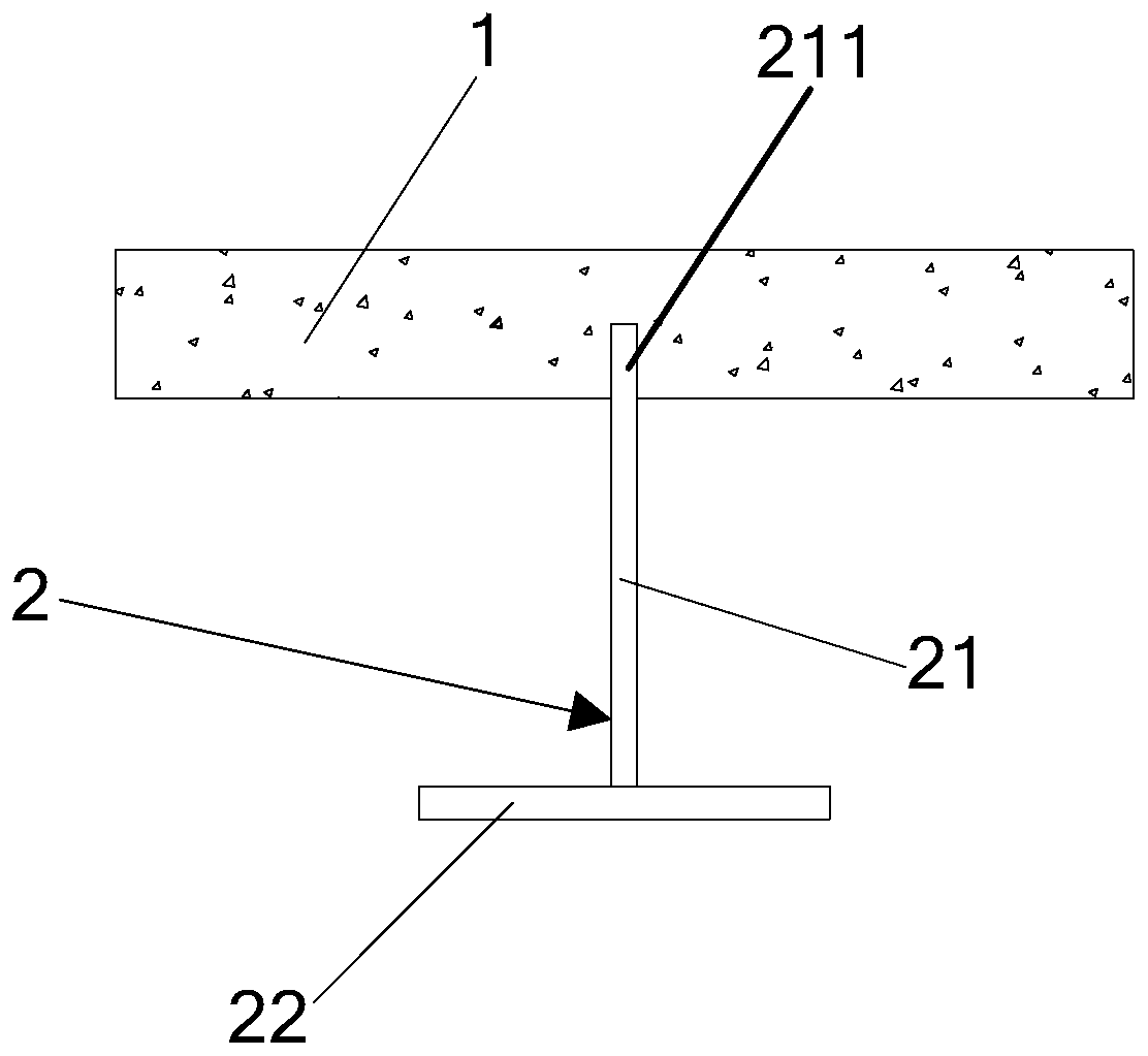
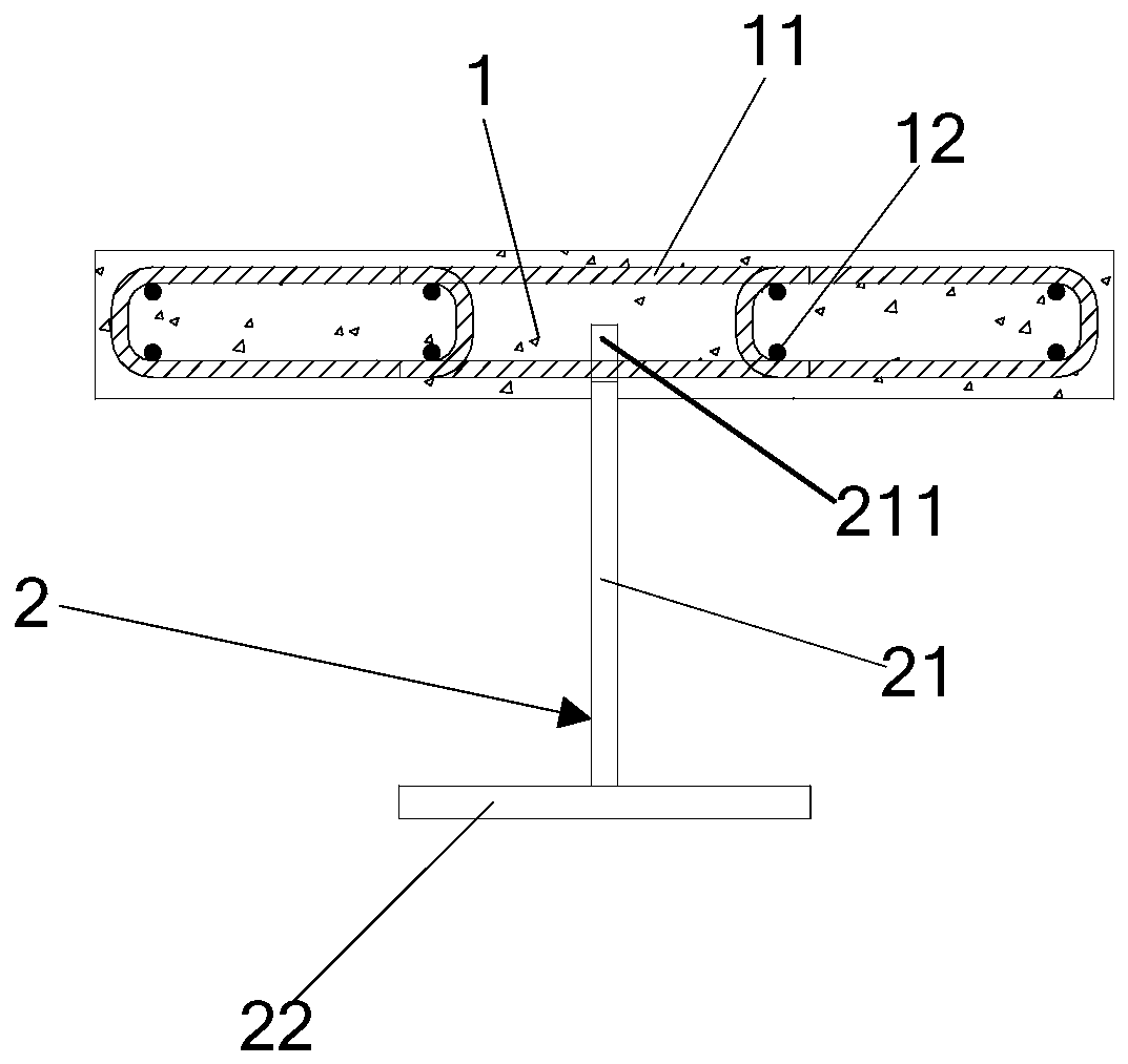
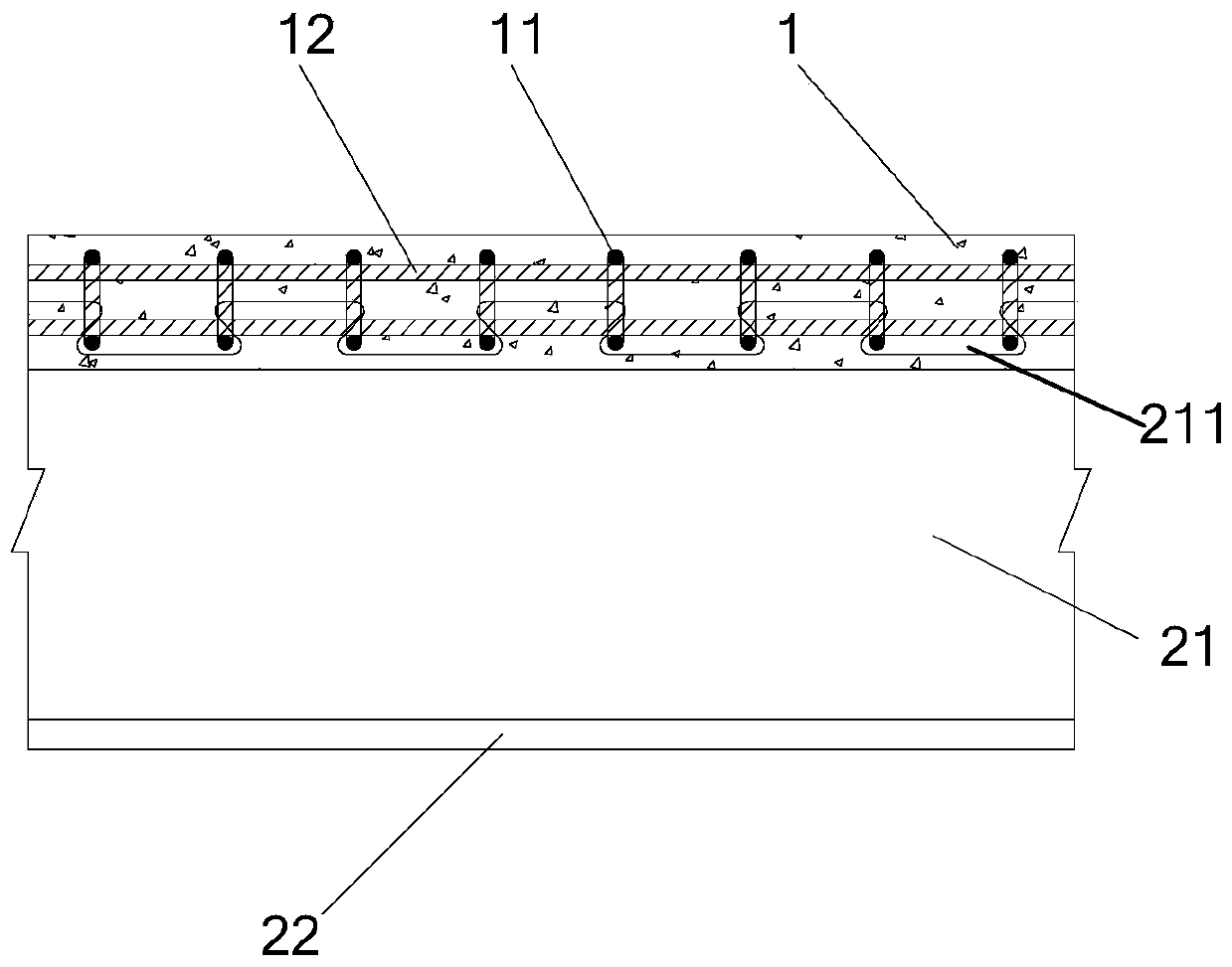
[0032] figure 1 It is a schematic left view of a composite beam in an embodiment of the present invention; figure 2 It is a left perspective schematic diagram of a composite beam in an embodiment of the present invention; image 3 It is a front perspective schematic diagram of a composite beam in an embodiment of the present invention, see Figure 1 to Figure 3 As shown, an embodiment of the present invention provides a composite beam, which includes,

[0033] The concrete slab 1 is provided with transverse steel bars 11 at intervals;

[0034] Inverted T-shaped steel beam 2, which includes:

[0035] - web 21, one side of which is provided with a connection part 211, the connection part 211 is located in the concrete slab 1, and the web 21 is connected to the transverse reinforcement 11 through the connection part 211;

[0036] - Flanges ...


PUM


Abstract

The invention relates to the field of bridge construction, and discloses a combined beam. The combined beam comprises a concrete plate, wherein transverse steel bars are arranged in the concrete plateat intervals. The combined beam further comprises an inverted T-shaped steel beam, the inverted T-shaped steel beam comprises a web plate and further comprises a wing plate, wherein a connecting partis arranged on one side of the web plate, the connecting part is arranged in the concrete plate, the web plate is connected with the transverse steel bars through the connecting part, and the wing plate is connected with the web plate in a perpendicular mode. The invention further discloses a manufacturing method of the combined beam. The mode that the connecting part is connected with the transverse steel bars in the concrete plate is adopted in the combined beam and is compared with the mode that shearing force nails are adopted to achieve the connection between a steel plate and a concreteplate, the advantages of being high in shear stiffness, high in bearing capacity, good in ductility and the like; and in addition, the combined beam is simple in structure, convenient and fast to construct, high in cracking strength and good in durability. According to the combined beam and the manufacturing method thereof, the defects that when the mode that the shearing force nails are adoptedto achieve the connection between the steel plate and the concrete plate is adopted, the shear resistance and the bearing capacity of a connecting piece are low, the shear stiffness is low, and the ductility is poor are overcome, and the problems that the concrete plate is prone to cracking, and the durability is poor are solved.

Description

technical field [0001] The invention relates to the field of bridge construction, in particular to a composite beam and a manufacturing method thereof. Background technique [0002] The composite beam is a beam structure composed of two different materials. The steel beam and the concrete slab are connected as a whole through shear connectors to bear the force together, which can give full play to the advantages of the steel in tension and the concrete slab in compression. It has the advantages of high bearing capacity, high rigidity, good seismic and dynamic performance, small component section size, and convenient construction. [0003] Traditional steel-concrete composite beams are composed of steel beams and reinforced concrete slabs, and are connected to the reinforced concrete slabs by welding shear studs on the upper flange of the steel beams. Steel-concrete composite beams can give full play to the characteristics of high tensile strength of steel beams and high com...

Claims


Application Information

Patent Timeline
Patent Type & Authority Applications(China)
IPC IPC(8): E01D19/00E01D21/00
CPCE01D19/00E01D21/00
Inventor 肖林高立强陈露一伍贤智王敏郑纲
Owner CHINA RAILWAY BRIDGE SCI RES INST LTD
Why Eureka
Try Eureka